AR26.40-D-2476A | Disassemble/assemble rear section of transmission housing | 16.6.10 |
Transmission 711.603
Transmission 711.612
Transmission 711.612
with CODE (N05) Power takeoff countershaft (2c) without flange
with CODE (N07) Power takeoff countershaft (2b) with flange
Transmission 711.613
Transmission 711.613
with CODE (N05) Power takeoff countershaft DB, (2c)
with CODE (N07) Power takeoff countershaft (2b) with flange

D26.30-0002-06
Transmission 711.603
1 Mounting bolt of guide plate
2 Guide plate
3 Circlip
4 Main shaft bearing
5 Cylindrical roller bearing sleeve
6 Rear section of transmission housing
7 Sealing ring
8 Oil drain plug
9 Cap
10 Sealing ring
11 Oil filler plug
12 Sealing ring

D26.30-0007-06
Transmission 711.612 /613 without power takeoff
1 Mounting bolt of guide plate
2 Guide plate
3 Circlip
4 Main shaft bearing
5 Tapered roller bearing outer race
6 Rear section of transmission housing
7 Sealing ring
8 Oil drain plug
9 Cap
10 Sealing ring
11 Oil filler plug
12 Sealing ring
13 Spacer sleeve
| Remove | ||
1 | Remove main shaft and countershaft | ||
| Disassemble | ||
2 | Remove guide plate (2) | On vehicles with power takeoff and shift lock, remove spacer sleeve (13) | |
3 | Remove circlip of mainshaft bearing (3) | ||
4 | Press out mainshaft bearing (4) using a suitable drift | The installation position of the mainshaft bearing is specified by the locating pin (arrow) | |
5 | Remove cap (9) and sealing ring (7) for induction-type pulse generator | On transmission 711.612 /613 with power takeoff (code N05 and N07) the pulse generator is fitted on the opposite side. | |
6 | Remove gear set and power takeoff shift mechanism | Transmission 711.612 /613 with code N05 and N07 (power takeoff). | |
Internal extractor | |||
Countersupport | |||
Socket wrench | |||
7.1 | Remove cylindrical roller bearing sleeve (5) | Transmission 711.603 | |
Internal extractor | |||
Countersupport | |||
7.2 | Remove tapered roller bearing outer race (5) | Transmission 711.612/ 613 | |
Internal extractor | |||
Countersupport | |||
| Assemble | ||
8 | Install gear set and power takeoff shift mechanism | Transmission 711.612 /613 with code N05 and N07 (power takeoff). | |
Socket wrench | |||
Press-in tool | |||
Long-life grease | |||
Loctite 270 sealant | |||
9 | Adjust axial play of driver | Transmission 711.612/ 613 Shims are available in the following thicknesses: 0.20; 0.30 mm | |
10.1 | Press in cylindrical roller bearing sleeve (5) using a suitable drift | Transmission 711.603 The transmission housing must be placed horizontally on a suitable base | |
10.2 | Press in tapered roller bearing outer race (5) using a suitable drift | Transmission 711.612/ 613 The transmission housing must be placed horizontally on a suitable base | |
11 | Install cap (9) and sealing ring (7) for induction-type pulse generator | Replace seal | |
12 | Press in mainshaft bearing (4) using drift | The transmission housing must be placed horizontally on a suitable base | |
| Anti-twist lock attached to the main shaft bearing | ||
13 | Install circlip of mainshaft bearing (3) | ||
14 | Install guide plate (2) | Pay attention to the correct position of the square bore. The square bore must align with the lowest bore (arrow) for the locking bolts of the shift rails Observe spacer sleeve (13) | |
| Install | ||
15 | Install/adjust mainshaft and countershaft |
Cover
Number | Designation | Transmission 711.603/612/613 | ||
BA26.30-N-1002-01B | Bolt, shift rail guide plate to transmission cover | M8 | Nm | 21 |


000 589 27 33 00
Internal puller
Internal puller
Internal puller
Counter stay
000 589 25 33 00
000 589 29 33 00
000 589 33 33 00
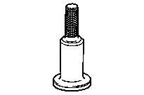


312 589 05 15 00
Socket wrench
Drift
Counter stay
Press-in tool
000 589 34 33 00
711 589 00 09 00
711 589 00 43 00
Repair materials
Number | Designation | Order number |
BR00.45-Z-1008-02A | Quick-acting adhesive, Loctite 270 | A 002 989 93 71 |
BR00.45-Z-1001-06A | Long-life grease | A 000 989 63 51 11 |