AR03.20-D-4351WE | Remove/install crankshaft | 26.7.11 |
ENGINES 651 in MODEL 900
ENGINES 651.955 /956 /957 in MODEL 906

D03.20-1189-06
1 Crankshaft
2 Cylinder crankcase
3 Bearing shells
4 Fitted bearing shell with thrust plates
5 Bearing shells
6 Fitted bearing shell with thrust plates
7 Crankshaft bearing cap
8 Bolts
9 Oil suction pipe
10 Connecting rod
11 Connecting rod bearing shell
12 Connecting rod bearing shell
13 Connecting rod bearing cap
14 Connecting rod bolts
Modification notes
21.6.11 | Special tool for counterholder 651 589 08 40 00 added | ||
21.6.11 | Special tool for counterholder 651 589 08 40 00 added |
| Removing | ||
1 | Remove engine and install on assembly stand | ||
2.1 | Remove flywheel | With transmission 711.680 | |
2.2 | Remove driven plate | On model 906 with transmission 722.686 | |
3 | Remove cylinder head cover | ||
4 | Remove cover on cylinder head | ||
5 | Remove timing case cover | ||
6 | Remove oil pan | ||
7 | Remove oil suction pipe (9) | ||
8 | Move engine to basic position and arrest | The hold-down device remains on the camshaft and the assembly tool remains on the Lanchester balance shaft in the crankshaft bearing cap (7). | |
| |||
Counterholder (with code (H08) High performance A/C or with code (HK4) Rear A/C, enhanced) | |||
Counterholder (without code (H08) High performance A/C or without code (HK4) Rear A/C, enhanced) | |||
Holddown device | |||
Assembly tool | |||
9 | Remove belt pulley/vibration damper | ||
10 | Remove bracket together with poly-V belt tensioning device | ||
11 | Remove end cover together with radial shaft sealing ring | ||
12 | Detach connecting rod bearing bolts (14) on connecting rod bearing cap (13) | ||
13 | Remove intermediate gear for the engine control | ||
14 | Unscrew bolts (8) in opposite order of tightening torque | ||
15 | Remove crankshaft bearing cap (7) | ||
16 | Remove bearing shells (5) and fitted bearing shells with thrust plates (6) from crankshaft bearing cap (7). | Mark bearing shells (5) and fitted bearing shells with thrust plates (6) in relation to corresponding crankshaft bearing. | |
17 | Mark connecting rods (10) in connecting rod bearing cap (13) on one side relative to each other for this step | If necessary, turn crankshaft (1) 180°. While rotating crankshaft (1) ensure that connecting rods (10) do not get caught. | |
18 | Unscrew connecting rod bearing bolt (14) and remove connecting rod bearing cap (13). | ||
19 | Remove connecting rod bearing shells (11, 12) | Mark upper connecting rod bearing shell (11) and lower connecting rod bearing shell (12) in relation to corresponding connecting rod bearing cap (13). Do not mix up connecting rod bearing shells (11, 12). | |
20 | Take crankshaft (1) out of crankcase (2) | Aid of helper required. | |
21 | Remove bearing shells (3) and fitted bearing shell with thrust plates (4) from cylinder crankcase (2) | Mark bearing shells (3) and fitted bearing shells with thrust plates (4) in relation to corresponding crankshaft bearing. | |
| Clean | ||
22 | Clean sealing surfaces and bearing surfaces on cylinder crankcase (2) and crankshaft bearing cap (7) | Do not use sharp-edged or pointed implements to clean. Damage can occur to the sealing and bearing surfaces otherwise. | |
Cold-sprayable cleaner | |||
| Measure | ||
23 | Measure crankshaft (1), mount in bearings | ||
| Checking | ||
24 | Check connecting rod bearing bolts (14) | ||
25 | Check bolts (8) on crankshaft bearing cap (7) | ||
| Install | ||
26 | Assign bearing shells (3, 5) and fitted bearing shells with thrust plates (4, 6) | When replacing bearing shells (3, 4)and fitted bearing shells with thrust plates (4, 6) or crankshaft (1). | |
| Bearing diagram for crankshaft | ||
27 | Insert bearing shells (3) and fitted bearing shells with thrust plates (4) into cylinder crankcase (2). | Lubricate bearing shells (3) and fitted bearing shell with thrust plate (4) Observe marking on bearing shells (3). | |
28 | Insert crankshaft (1) in crankcase (2) | Aid of helper required. | |
29 | Lubricate connecting rod bearing shells (11) and insert into connecting rods (10). | Insert the connecting rod bearing shells (11) untilted into the connecting rods (10). Connecting rod bearing damage may occur otherwise. | |
Observe assignment of connecting rod bearing shells (11) in relation to connecting rods (10). | |||
30 | Insert connecting rod bearing shells (12) into connecting rod bearing cap (13) | Insert connecting rod bearing shells (12) untilted into the connecting rod bearing cap (13). Connecting rod bearing damage may occur otherwise. | |
Observe marking on connecting rod bearing shells (12) in relation to connecting rod bearing caps (13). | |||
31 | Position connecting rod bearing cap (13) on crankshaft (1) and connecting rod (10) and screw in connecting rod bearing bolts (14) | Assemble connecting rod bearing cap (13) and connecting rods (10) according to provided markings. Connecting rod bearing cap (13) and connecting rods (10) are cracked (broken) and should not be mixed up or installed with sides mixed up to prevent decreasing dimensional accuracy. | |
Tighten connecting rod bearing bolts (14) only to first and second stage tightening torque. | |||
| |||
32 | Insert bearing shells (5) and fitted bearing shells with thrust plates (6) into crankshaft bearing cap (7). | Lubricate bearing shells (5) and fitted bearing shell with thrust plate (6) Observe marking on bearing shells (5). | |
33 | Install crankshaft bearing cap (7) with arrested Lanchester balance shafts on cylinder crankcase (2) | Ensure that fitted sleeve is seated correctly. | |
34 | Tighten bolts (8) according to tightening procedure of crankshaft bearing cap (7) | Lubricate bolts (8) on thread and bolt head contact surface. | |
| |||
35 | Tighten connecting rod bearing bolts (14) of connecting rod cap(13) to third stage tightening torque | ||
| |||
36 | Install end cover together with radial shaft sealing ring | ||
37 | Install carrier with poly-V belt tensioning device | ||
38 | Install belt pulley/vibration damper | ||
39 | Turn crankshaft (1) with counterholder to top dead center position on 1st cylinder | ||
Counterholder (with code (H08) High performance A/C or with code (HK4) Rear A/C, enhanced) | |||
Counterholder (without code (H08) High performance A/C or without code (HK4) Rear A/C, enhanced) | |||
40 | Install intermediate gear on engine timing | ||
41 | Install oil suction pipe (9) | ||
42 | Install oil pan | ||
43 | Install timing case cover | ||
44 | Install cover on cylinder head | ||
45 | Install cylinder head cover | ||
46.1 | Install flywheel | With transmission 711.680 | |
46.2 | Install drive plate | On model 906 with transmission 722.686 | |
47 | Remove engine from assembly stand and install in vehicle |
Test specifications for connecting rod bolts
Number | Designation | Engine | |||
BE03.10-N-1001-03D | Connecting rod bolt | Thread diameter | M | 81 | |
Shank length | New | mm | 47 (0.3) | ||
max. | mm | 48 | |||
Check values for crankshaft bearing cap bolts
Number | Designation | Engine | ||
BE03.20-N-1003-01G | Crankshaft bearing cap bolts M12 | Thread diameter | M | 12 |
Length (L) when new | mm | 104.7 to 105.3 | ||
Max. length (L) | mm | 106.5 | ||
See picture | ||||
Connecting rod
Number | Designation | Engine 651 in model 900 | Engine 651 in model 639, 906 | |||
BA03.10-N-1001-01N | Bolt, connecting rod bearing cap to connecting rod | At initial tightening torque | Stage 1 | Nm | 5 | 5 |
Stage 2 | Nm | 25 | 25 | |||
Stage 3 | ° | 180 | 180 | |||
For subsequent tightening | Stage 1 | Nm | 5 | 5 | ||
Stage 2 | Nm | 25 | 25 | |||
Stage 3 | ° | 90 | 90 | |||
Crankshaft
Number | Designation | Engine | Engine 651 | |||
BA03.20-N-1001-01J | Bolt for crankshaft bearing cap | M11 | Stage 1 | Nm | - | - |
Stage 2 | ° | - | - | |||
M12 | Stage 1 | Nm | 60 | 60 | ||
Stage 2 | ° | 90 | 90 | |||
Camshaft
Number | Designation | Engine | Engine | ||
BA05.20-N-1002-01O | Bolt connecting camshaft bearing cap to cylinder head | Nm | 9 | 9 | |
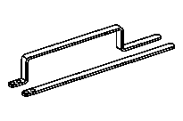
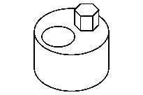


651 589 08 40 00
Holddown device
Counterholder
Counterholder
Assembly tool
651 589 00 40 00
651 589 01 40 00
651 589 02 63 00
Repair materials
Number | Designation | Order number |
BR00.45-Z-1001-04A | Cold-sprayable cleaner | Henkel Loctite Deutschland GmbH |
참조 문서
- ah0320n435101we 크랭크 샤프트의 베어링 위치도
- ar0110d100001we 엔진을 상사점으로 돌리기
- ar0110d2401we 변속기와 함께 엔진 탈, 장착
- ar0120d5014we
- ar0130d5701we 실린더 헤드 커버 탈, 장착
- ar0140d8000we 컨트롤러 하우징 커버 탈, 장착
- ar0140d8920we
- ar0145d7500we 오일팬 탈, 장착
- ar0310d611101us 커넥팅 로드 나사를 점검하십시오.
- ar0310s611102sd 커넥팅 로드 볼트 조이기
- ar0320d435102we 크랭크 샤프트 베어링 캡 조임 순서
- ar0320d435103we 크랭크 샤프트 베어링 캡 볼트 점검
- ar0320d4355we 크랭크 샤프트 측정 및 고정
- ar0320d436001we 크랭크 샤프트 베어링 쉘 배열
- ar0330d1600we 벨트 풀리/진동 댐퍼 탈, 장착
- ar0330d8002we 플라이 휠 탈, 장착
- ar0330d8003we
- ar0510d762001we 엔진을 기본 위치에 놓기, 고정하기
- ar0510d7620we
- ar1325d3300we V 벨트 텐셔닝 장치가 장착된 캐리어 탈, 장착
- ar1810d4020we