AR26.45-D-0016B | Disassemble/assemble PTO | 12.4.10 |
TRANSMISSION 711.651 in MODEL 906 with ENGINE 646.984 /985 /986 /989 with CODE (N05) Power take-off countershaft (2c) without flange
TRANSMISSION 711.651 in MODEL 906 with ENGINE 646.984 /985 /986 /989 with CODE (N07) Power take-off countershaft (2b) with flange
TRANSMISSION 711.660 in MODEL 906 with ENGINE 642.992, 646.985 /986 /989 with CODE (N05) Power take-off countershaft (2c) without flange
TRANSMISSION 711.660 in MODEL 906 with ENGINE 642.992, 646.985 /986 /989 with CODE (N07) Power take-off countershaft (2b) with flange
TRANSMISSION 711.680 in MODEL 906 with CODE (N05) Power take-off countershaft (2c) without flange
TRANSMISSION 711.680 in MODEL 906 with CODE (N07) Power take-off countershaft (2b) with flange
TRANSMISSION 711.685 in MODEL 906 with CODE (N05) Power take-off countershaft (2c) without flange
TRANSMISSION 711.685 in MODEL 906 with CODE (N07) Power take-off countershaft (2b) with flange
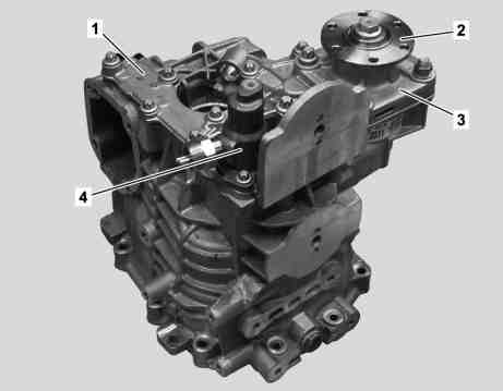
D26.45-1020-11
Shown on transmission 711.680 with CODE (N07) Power take-off countershaft (2b) with flange
1 Housing cover
2 Output flange
3 Bearing cap
4 Shift cylinder
| Removing | ||
1 | Remove the transmission | Transmission 711.651/660 | |
Transmission 711.680/685 | |||
2 | Attach transmission to assembly stand | ||
3 | Remove front section of transmission housing | Refer to Disassemble/assemble transmission housing. | |
Transmission 711.651/660 | |||
Transmission 711.680/685 | |||
4 | Remove shift shaft | Transmission 711.680/685 | |
5 | Remove main shaft and countershaft with shift unit | Transmission 711.651/660 | |
Transmission 711.680/685 | |||
| Disassemble | ||
6 | Remove output flange (2) with radial shaft sealing ring | Only with code (N07) Power take-off countershaft (2b) with flange. | |
7 | Remove shift cylinder (4) | ||
8 | Remove gearshift lever and shift rod of the shift lock | Transmission 711.651/660 | |
9 | Remove and disassemble bearing cap (3) | Only with code (N07) Power take-off countershaft (2b) with flange. | |
| |||
| |||
10 | Remove gear set and shift mechanism of power take-off | ||
| |||
| |||
| |||
| |||
| |||
| |||
| Clean | ||
11 | Clean bearing seats | Use clean, lint-free rags. | |
12 | Clean sealing surfaces of housing parts | The sealing surfaces must be grease-free. | |
| Assemble | ||
Danger! | Risk of injury to skin and eyes caused by handling hot or glowing objects. | Wear safety gloves, protective clothing and safety glasses, if necessary. | |
13 | Install gear set and shift mechanism of power take-off | ||
| |||
| |||
14 | Determine adjustment shim thickness for output shaft | Only with code (N07) Power take-off countershaft (2b) with flange. | |
| |||
| |||
15 | Install the bearing cap (3) | Only with code (N07) Power take-off countershaft (2b) with flange. | |
| |||
| |||
16 | Install gearshift lever and shift rod of the shift lock | Transmission 711.651/660 | |
| |||
17 | Install shift cylinder (4) | ||
| |||
18 | Install output flange (2) with radial shaft sealing ring | Only with code (N07) Power take-off countershaft (2b) with flange. | |
| Install | ||
19 | Install main shaft and countershaft with shift unit | Transmission 711.651/660 | |
Transmission 711.680/685 | |||
20 | Install shift shaft | Transmission 711.680/685 | |
21 | Install front section of transmission housing | Refer to Disassemble/assemble transmission housing. | |
Transmission 711.651/660 | |||
Transmission 711.680/685 | |||
22 | Install transmission | Transmission 711.651/660 | |
Transmission 711.680/685 |
Test values for PTO
Number | Designation | Trans-mission 711.651 | Trans-mission 711.660 | Trans-mission 711.680 | Trans-mission 711.685 | |
BE26.45-N-1003-01E | Initial tension for output shaft on power takeoff | mm | 0.0 to 0.1 | 0.0 to 0.1 | 0.0 to 0.1 | 0.0 to 0.1 |
PTO
Number | Designation | Transmissions 711.651/660 with code N05, N07 | Transmissions 711.680/685 with code N05, N07 | |
BA26.45-N-1002-01A | Bearing cap or hydraulic pump on power takeoff | Nm | 46 | 46 |
BA26.45-N-1009-01A | Bolt, power take-off housing cover | Nm | 28 | 28 |
BA26.45-N-1010-01A | Bolt, shift cylinder to power take-off | Nm | 28 | 28 |
BA26.45-N-1011-01A | Bolt, gearshift lever of shift lock to transmission housing | Nm | 23 | - |


000 589 29 33 00
Extraction claw
Internal puller
Counter stay
Impact extractor
000 589 34 33 00
716 589 03 33 00
355 589 01 63 00


000 589 33 33 00
Drift
Counter stay
Internal puller
Strip clamp
000 589 27 33 00
711 589 11 15 00
000 589 59 63 00

Parallel support
168 589 03 21 00
Repair materials
Number | Designation | Order number |
BR00.45-Z-1015-01A | Loctite 5203 sealant | A 002 989 71 20 10 |
BR00.45-Z-1028-04A | Cleaner from package | Adolf Würth GmbH & Co. KG |
Referenced documents
- ar2610d0020g Remove/install transmission
- ar2610d0020h Remove/install transmission
- ar2610d0036a Fasten transmission on assembly stand
- ar2640d2002d Disassemble/assemble transmission housing
- ar2640d2002e Disassemble/assemble transmission housing
- ar2645d001006a Remove/disassemble power take-off bearing cap
- ar2645d001007c Remove gear set and shift mechanism of power take-off
- ar2645d001008c Install gear set and shift mechanism of power take-off
- ar2645d0011b Remove/install radial shaft seal for output flange
- ar2645d001503a Install power take-off bearing cap
- ar2645d001506a Determine adjustment shim thickness for output shaft
- ar2645d001604a Remove/install gearshift lever and shift rod of the shift lock
- ar2645d002002b Remove/install shift cylinder.
- ar2650d0002a Remove/install main shaft and countershaft with shift unit
- ar2650d0002b Remove/install main shaft and countershaft with shift unit
- ar2660d6500a Remove/install shift shaft
- as0000z000201a Risk of injury. Skin or eye injuries may result when handling hot or glowing objects.