Modification notes |
26.09.2013 | Special tool drift added. | Operation step 16, 19 | 715 589 09 15 00 |
17.09.2013 | "Remove assembly device (73) from transmission (72) and place transmission (72) horizontally" added. | Operation step 28 | AR26.10-W-0001-01HE |
17.09.2013 | "Install oil restrictor (69) at main shaft (21)" added. | Operation step 38 | AR26.50-W-0004H |
28.11.2013 | Getriebegehäuse Vorderteil an Getriebegehäuse Mittelteil | GETRIEBE 715.370/380 | BA26.40-N-1001-01KL |

W26.50-1134-09
Shown on transmission 715.370 with code GE3 (Mercedes PowerShift) |
1 | Countershaft brake | 11 | Oil pipe | 21 | Main shaft (with shift unit) | ||
2 | Tapered roller bearing outer race | 12 | Countershaft | 22 | Synchronizer cone with synchronizer and annular spring | ||
3 | Drive shaft bearing cap | 13 | Tapered roller bearing outer race | 23 | Sliding sleeve | ||
4 | Tapered roller bearing outer race | 14 | Reverse gear | 24 | Drive shaft | ||
5 | Release lever | 15 | Range group | 25 | Shift | ||
6 | Splitter group shift rod | 16 | Reverse idler shaft | 26 | Bearing pin for splitter group shift fork | ||
7 | Front section of transmission housing | 17 | bearing bolt (reverse/1st gear shift fork and 2nd/3rd gear shift fork) | B3 | Countershaft rpm sensor | ||
8 | Retaining ring | 18 | Center section of transmission housing | B47 | Transmission oil temperature sensor | ||
9 | Shift fork for splitter group | 19 | Shim | B62 | Splitter sensor (SSP) | ||
10 | Sliding blocks | 20 | Tapered roller bearing outer race |

7 | Front section of transmission housing |
30 | Shift rail (reverse/1st gear) |
31 | Shift rail (2nd/3rd gear) |
32 | Shift rail guide |
33 | Holding device |
W26.60-1246-02

21 | Main shaft |
69 | Oil restrictor |
W26.50-1214-06

72 | Transmission |
73 | Assembly device |
W26.50-1216-12
Notes on compressed air connection systems | |||
| Assemble | ||
1 | Assemble countershaft (12) | ||
2 | Assemble (24) drive shaft | ||
3 | Assemble main shaft (21) | ||
4 | Install tapered roller bearing outer races (13, 20) and spacer washer (19) in center section of transmission housing (18) | Use a suitable drift. The tapered roller bearing outer races (13, 20) must be installed from inside in the center section of transmission housing (18). | |
Grease, silicone-based, 100 g | |||
5 | Install reverse idler gear (14) with bearing and bush | The long collar of the reverse gear (14) must point towards the output. | |
6 | Use retainer (33) to insert main shaft (21) and countershaft (12) into center section of transmission housing (18) | ||
Clamping device | |||
Retaining device | |||
7 | Install both bearing bolts (17) | Insert bearing bolt (17) with quick-action adhesive. | |
Shift fork bearing bolt to transmission housing | |||
Thread locking agent, Loctite 243 (10 ml) | |||
8 | Remove holding device (33) from main shaft (21) and from countershaft (12) | ||
9 | Place synchronizer cone (with synchronizer ring and annular spring (22)) onto main shaft (21) | ||
10 | Install sliding sleeve (23) | The long collar must point towards the output. | |
11 | Install drive shaft (24) | When doing so, push the countershaft (12) to one side. | |
Grease, silicone-based, 100 g | |||
12 | Center reverse idler gear (14) and insert reverse idler shaft (16) | Retaining plate of reverse shaft to transmission housing | |
13 | Install oil pipe (11) | ||
14 | Install splitter group shift fork (9) with sliding blocks (10) | ||
15 | Insert alignment punch into the oil pipe (11) | Alignment punch | |
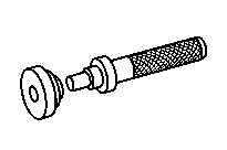
16 | Screw drift into front section of transmission housing (7) | Drift | |
17 | Mount front section of transmission housing (7) onto center section of transmission housing (18) | Coat sealing surfaces with sealant. | |
Loctite 5203 sealant | |||
18 | Install circlip (8) on oil pipe (11) and remove the centering drift from oil pipe (11) | ||
19 | Remove drift from transmission housing front section (7) and screw in bolts around circumference of transmission housing | Pay attention to different lengths of bolts. | |
Transmission housing front part to transmission housing center part | |||
Drift | |||
20 | Install tapered roller bearing outer races (2, 4) as far as the stop | Use a suitable drift. | |
Grease, silicone-based, 100 g | |||
21 | Install radial shaft sealing ring and pilot bushing for splitter group shift rod (6) | ||
Synthetic grease 50 g | |||
Drift | |||
22 | Install splitter group shift rod (6) | ||
The splitter group shift fork (9) must engage in the recess in the splitter group shift rod (6). | |||
Splitter group shift rod lock to transmission housing | |||
Shift fork bearing bolt to transmission housing | |||
Thread locking agent, Loctite 243 (10 ml) | |||
Loctite 5203 sealant | |||
23 | Use holding device (33) to fix shift rails (30, 31) in the neutral position on the shift rail guide (32) | Retainer | |
24 | Pull out splitter group shift rod (6) using assembly tool until splitter position is engaged | ||
| Assembly tool for installing splitter group shift rod | ||
25 | Determine shims of input shaft (24) and countershaft (12) | ||
Drive shaft bearing pretension | |||
Setting tolerance of bearings on countershaft | |||
Preload of bushings on drive shaft and countershaft for determining shims | |||
Torque screwdriver | |||
Clamping plates | |||
26 | Install countershaft brake (1) with determined shim | ||
The oil grooves of brake disks must be aligned. | |||
27 | Install bearing cap of input shaft (3) with the shim determined | ||
28 | Remove assembly device (73) from transmission (72) and place transmission (72) horizontally | ||
Assembly device | |||
29 | Determine shim for shift piston of splitter group | ||
Adjustment dimension for gearshift piston of cascade box | |||
30 | Pull out splitter group shift rod (6) using assembly tool until splitter position is engaged | ||
| Assembly tool for installing splitter group shift rod | ||
31 | Install rubber sealing ring and shift piston | Coat rubber sealing ring with synthetic grease. | |
Shift piston to splitter group shift rod | |||
Synthetic grease 50 g | |||
Quick-acting adhesive, Loctite 270 | |||
Puller | |||
32 | Determine shim for shift cylinder of splitter group | ||
Adjustment dimension for splitter box shift cylinder | |||
Synthetic grease 50 g | |||
Internal extractor | |||
Counter stay | |||
33 | Remove holding device (33) | ||
34 | Install shift mechanism (25) | ||
35 | Install transmission oil temperature sensor (B47) | Transmission oil temperature sensor to transmission housing | |
36 | Install countershaft speed sensor (B3) |
| |
Vehicles with code GE7 (Mercedes PowerShift 2) | |||
37 | Install rpm sensor of main shaft (21) | Only on vehicles with code GE7 (Mercedes PowerShift 2). | |
38 | Install oil restrictor (69) on main shaft (21) | ||
39 | Assemble range group (15) | ||
40 | Install range group (15) | ||
41 | Attach compressed air line to gear module, gate module, shift cylinder of range group and power take-off | ||
42 | Mount electrical line onto connectors and holders | ||
43 | Install release lever (5) | Release lever to transmissionRelease lever to transmission |


715 589 08 31 00
Assembly device
715 589 03 15 00
Alignment punch
000 589 30 33 00
Internal extractor
714 589 05 15 00
Drift


001 589 80 21 00
Torque screwdriver
715 589 02 07 00
Puller
315 589 02 31 00
Clamping device
715 589 09 15 00
Drift


715 589 01 31 00
Retaining device
715 589 18 63 00
Retainer
715 589 15 63 00
Clamping plates
000 589 34 33 00
Counter stay
Repair materials |
Number | Designation | Order number |
BR00.45-Z-1008-02A | Quick-acting adhesive, Loctite 270 | A 002 989 93 71 |
BR00.45-Z-1008-06A | Grease, silicone-based, 100 g | A 001 989 28 51 |
BR00.45-Z-1015-01A | Loctite 5203 sealant | A 002 989 71 20 10 |
BR00.45-Z-1027-06A | Synthetic grease 50 g | A 001 989 32 51 10 |
BR00.45-Z-1133-02A | Thread locking agent, Loctite 243 (10 ml) | A 613 989 09 71 09 |
Referenced documents
- ah0018n000101a Notes on compressed air connection systems
- ar2610w000101he Attaching and detaching mounting device on transmission
- ar2619w0018a Remove/install countershaft speed sensor
- ar2619w0018kc Remove/install countershaft speed sensor
- ar2619w0026kc Remove/install transmission main shaft rpm sensor
- ar2630w1020kb Remove/install input shaft bearing cap
- ar2631w3102a Install range group
- ar2631w3201a Assembling range group
- ar2635w100001a Determine shim for shift piston of splitter group
- ar2635w100002a Determine shim for cylindrical actuator of cascade box
- ar2635w100003a Remove/install radial shaft seal and pilot bushing for splitter group shift rod
- ar2635w100004a Install shift rod of splitter group
- ar2650w0004h Remove/install oil restrictor on main shaft
- ar2650w041003kb Determine shims of drive shaft and countershaft
- ar2650w0426kc Assembling transmission main shaft
- ar2650w400002kc Install main shaft and countershaft with shift unit
- ar2650w4744kb Dismantle, assemble drive shaft.
- ar2650w4775kc Disassemble, assemble countershaft
- ar2650w6000kb Remove/install countershaft brake (VGW-B)
- ar2660w0001h Remove and install gearshift system
- wf5850n263501a Assembly tool for installing splitter group shift rod