
P05.30-2163-09
Shown on engine 611.960 |
1 | Valve assembly tool | 14 | Upper valve spring retainer | 18 | Valve stem seal | ||
3 | Retaining lock | 15 | Valve springs | 21 | Connector | ||
13 | Cylinder leakage tester | 16 | Valve keeper |

Shown on engine 611.960 |
13 | Cylinder leakage tester |
19 | Drift |
20 | Pliers |
21 | Connector |
P05.30-2164-06
| Remove/install | ||
1 | Remove camshafts. | ||
2.1 | Turn engine at the crankshaft with the counterholder in the direction of engine rotation and place the piston of the cylinder to be processed at top dead center (TDC). | Engine 651 in model 166, 172, 204, 207, 212, 218, 221 | |
| |||
| |||
Counterholder | |||
2.2 | Turn engine in the direction of engine rotation at the crankshaft using a suitable tool and place the piston of the cylinder to be processed at top dead center (TDC). | Engine 651 in model 166, 172, 204, 207, 212, 218, 221 | |
| |||
| |||
3 | Install retaining lock (3) for crankshaft or ring gear. | ||
4 | Seal injector bore with connector (21). | Mounting of the connector (21) takes place by means of a genuine clamping claw of the engine 642, for which the bore was drilled with a diameter of 7.5 mm. | |
Connector | |||
5 | Connect cylinder leakage tester (13) to connector (21). | Pressurize compression chamber of the cylinder to be processed to approx. 5 bar. | |
Compression tester | |||
6 | Put together assembly tool valves (1) and attach to the cylinder head. | Use parts 3, 5, 7, 12 and 19 from valve assembly tool case. | |
Screw retaining fork M615 mm (part 12) at the edge of the cylinder head into the thread and position thrust piece for the detent compressor (part 7) vertically on the upper valve spring retainer (14). | |||
Valve assembly tools kit | |||
7 | Press together valve springs (15) with assembly tool valves (1). | ||
8 | Remove valve keepers (16). | Installation: | |
Use tweezers or a magnetic finger. | |||
Magnetic finger | |||
9 | Remove upper valve spring retainer (14) and valve springs (15). | Valves must not rest on the piston crown. Check upper valve spring retainer (14) for pitting and replace if necessary. | |
10 | Remove the valve stem seals (18) using pliers (20). | Installation: Use new valve stem seals (18). | |
Pliers | |||
Drift | |||
| Check | ||
11 | Check shaft surface of the valves for roughness and ridging. | ||
General information on checking valves, valve seats and valve guides | |||
Visual inspection or a nail check. | |||
If valves with a rough shaft surface or ridging are present, | |||
| |||
Replace valves. | |||
Remove/install valves | |||
12 | Install in the reverse order. |


001 589 78 21 00
Compression tester
611 589 00 63 00
Connector
111 589 25 61 00
Valve assembly tools kit
116 589 06 63 00
Magnetic finger


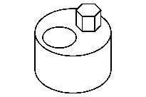
604 589 00 43 00
Drift
606 589 00 37 00
Pliers
651 589 00 40 00
Counterholder
Referenced documents
- ah0530p100002sz General information on checking valves, valve seats and valve guides
- ar0330p5000cd Remove/install retaining lock for crankshaft/ring gear
- ar0520p6992cd Remove/install camshafts
- ar0530p3511cd Remove/install valves