AR20.10-D-2460WE | Remove/install coolant thermostat | 23.5.11 |
ENGINES 651 in MODEL 900
ENGINES 651.955 /956 /957 in MODEL 906

D20.10-1123-09
1 Coolant thermostat
2 Coolant hose
3 Cable duct of engine wiring harness
4 Electrical connector
B11/17 Coolant temperature sensor
R48/2 Thermostat heating element
5 Electrical connector
6 Coolant hose
7 Coolant hose
D20.10-1124-09
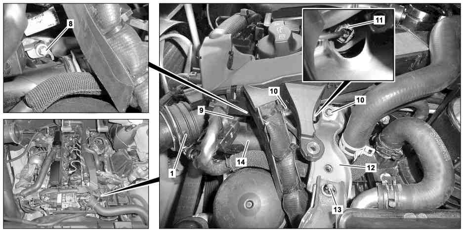
1 Coolant thermostat
8 Bolt
9 Electrical connector
13 Bolt
14 Coolant hose
10 Bolt
11 Electrical connector
12 Bracket

D20.10-1125-06
1 Coolant thermostat
15 Connecting piece
16 Connection fitting
17 Bolts
18 Carrier
Modification notes
21.5.10 | Repair method has been revised | ||
"Remove engine wiring harness cable duct" added | Step 5 | ||
"Special tool set, flexible head wrench 001 589 81 09 00 and basic data" added | Step 11 | ||
"Basic data" added | Operation step 13 |
| Remove/install | ||
Danger! | Risk of injury to skin and eyes caused by scalding from contact with hot coolant spray. Risk of poisoning caused by swallowing coolant. | Do not open cooling system unless coolant temperature is below 90°C. Open cap slowly and release the pressure. Do not pour coolant into beverage containers. Wear protective gloves, protective clothing and safety glasses. | |
1 | Remove engine trim panel | Installation: Only install engine cover after checking for leaks. | |
2 | Drain coolant | ||
3 | Open Henn coupling and remove coolant hose (2) on coolant thermostat (1) | Installation: Install new sealing ring. | |
4 | Pull coolant hoses (6, 7) off of coolant thermostat (1) and place aside | Installation: check clamps and coolant hoses (6, 7) for damage, replace if necessary. | |
Hose clamp pliers | |||
5 | Detach engine wiring harness cable duct (3) | ||
6 | Disconnect electrical connector (5) at coolant temperature sensor (B11/17) | ||
7 | Disconnect electrical connector (4) from heating element thermostat (R48/2) | ||
8 | Disconnect electrical connector (9) | ||
9 | Disconnect electrical connector (11) on glow plug cylinder 1 | Pull off old version electrical connector (11) with pliers. Pull off new version electrical connector (11) with commercially available needle nose pliers. | |
Pliers | |||
10 | Unscrew bolt (8) | ||
11 | Remove bolts (10, 13) and bracket (12) | | |
| |||
Flexible head wrench set | |||
12 | Detach coolant hose clamp (14) | Installation: Check coolant hose (14) and clamp for damage; replace if necessary. | |
13 | Remove screws/bolts (17) | | |
14 | Pull coolant thermostat (1) out of carrier (18), remove coolant hose (14) and coolant thermostat (1) | Installation: Replace connection piece (15) and sealing ring on connection fitting (16). | |
15 | Remove coolant temperature sensor (B11/17) | When replacing coolant thermostat (1). | |
16 | Install in the reverse order | ||
17 | Inspect cooling system for leaks |
Exhaust gas recirculation
Number | Designation | Engine | Engine | ||
BA14.20-N-1027-01H | Bolt, exhaust gas recirculation cooler/vacuum reservoir bracket to support brace | Nm | 9 | 9 | |
BA14.20-N-1028-01H | Bolt, support to cylinder head | Nm | 9 | 9 | |
Coolant pump, coolant thermostat
Number | Designation | Engine | Engine | ||
BA20.10-N-1006-01Q | Bolt, coolant connection fitting to cylinder head | Nm | 10 | 10 | |


003 589 03 37 00
Pliers
Hose clamp pliers
Flexible head wrench set
001 589 81 09 00
611 589 00 37 00
Henviste dokumenter
- ar0100d241101we
- ar0110d2405we
- ar0941p131101al
- ar2000d1140sd
- ar2000s1010s
- as2000z000101a Risiko for skoldningsskader på hud og øjne pga. sprøjtende, varm kølervæske. Risiko for forgiftning ved indtagelse af kølervæske