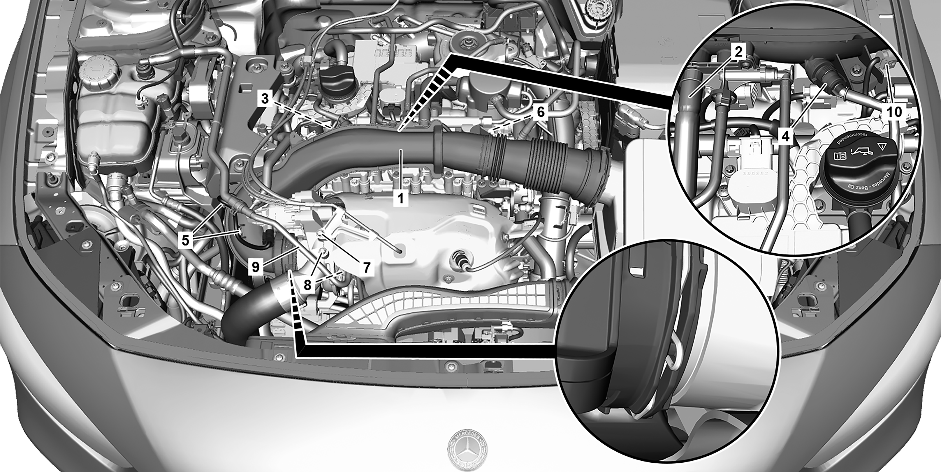
P09.10-A024-09
Shown on engine without code M016 (performance-enhanced engine) |
1 | Engine air intake duct | 6 | Ball stud | |
2 | Vent line | 7 | Screw | |
3 | Screw | 8 | Bolts | |
4 | Vent line | 9 | Coolant line | |
5 | Retaining clips | 10 | Electrical connector |

Shown on engine with code M016 (Uprated engine) |
11 | Shaped hose |
P09.10-A025-05
Warning | Risk of injury to skin and eyes suffering scalding from contact with hot coolantspray. Risk of poisoning from swallowing coolant. | Do not open cooling system unless coolant temperature is below 90 °C. Open cap slowly and release the pressure. Do not pour coolant into beverage containers. | |
Warning | Risk of injury. Skin or eye injuries may result when handling hot or glowing objects. | Wear protective gloves, protective clothing and safety glasses, if necessary. | |
Caution | Risk of injury caused by scraping or cutting body parts on sharp vehicle parts | Always wear protective gloves when working on or near sharp and non-deburred vehicle parts. | |
Caution | Risk of injury to skin and eyes due to handling of engine oil. Risk of poisoning caused by swallowing engine oil | Wear protective gloves, protective clothing and safety glasses. | |
Topical note | Information on preventing damage to electronic components due to electrostatic discharge | ||
Topical note | Notes on avoiding damage through contamination and foreign objects | ||
Topical note | Notes on coolant | ||
Topical note | Notes on threaded connections fastened using a tightening angle-based tightening process | ||
| Remove/install | ||
1 | Remove the bleed line (2) of the full-load crankcase ventilation system from the engine air intake duct (1) and place it to one side with the lines still attached. |
| |
Engine 260 in model 118, 177, 247 | |||
Installation: Only install upper engine cover after the leak test. | |||
2 | Remove the molded hose (11) and seal the openings with protective covers. | Engine 260 | |
Set of protective caps | |||
Hose clamp pliers | |||
3 | Unscrew the screw (3) and ball pin (6). | Screw/bolt, charge air distributor to cylinder head | |
4 | Remove the bleed line (4) from the engine air intake duct (1) and seal the openings with suitable stop plugs and protective covers. | Record plug | |
Set of protective caps | |||
5 | Release and disconnect the electrical connector (10) on the pressure sensor downstream of the air filter (B28/11). | ||
6 | Unscrew the screw (7) and place the inerting line to one side. | Engine 260 in model 118, 177, 247 | |
Bolt/nut for inerting system gas line to engine/body | |||
7 | Unclip the electric line from the retaining clips (5) and release and disconnect the electrical connector on the boost pressure control flap actuator (M16/7). | ||
8 | Unscrew the screws (8), remove the coolant line (9), place to one side and seal the openings with suitable stop plugs. | Installation: Replace screws (8). | |
Collect escaping coolant with rags. | |||
Installation: Replace seal. | |||
Bolt, feed line/return line to turbocharger/crankcase | |||
Record plug | |||
9 | Remove engine air intake duct (1). | ||
10 | Turn the pressure sensor downstream of the air filter (B28/11) on the engine air intake duct (1) counterclockwise and remove. | If engine air intake duct (1) is replaced. | |
Installation: Make sure that the sealing ring is seated correctly. | |||
11 | Check the sealing ring of the pressure sensor downstream of the air filter (B28/11) for damage. | If engine air intake duct (1) is replaced. | |
If there are problems, | |||
| |||
Replace the pressure sensor downstream of the air filter (B28/11). | |||
12 | Install in the reverse order. | ||
13 | Read out and delete fault memory. | ||
| |||
14 | Bleed coolant circuit. | ||
Cooler vacuum filling device | |||
Electric vacuum pump | |||
Test cap | |||
NTKL Adaption | |||
Warning | Risk of accident from vehicle starting off by itself when engine running. Risk of injury (bruises and burns) resulting from working on the engine while it is being started or when it is running. | Secure vehicle to prevent it from starting off by itself. Wear closed and snug-fitting work clothes. Do not touch hot or rotating parts. | |
15 | Perform engine test run. While doing so, check engine for proper operation and leak tightness. | ||
16 | Install upper engine cover. | ||
|


285 589 01 21 00
NTKL Adaption
454 589 00 37 00
Hose clamp pliers
210 589 00 91 00
Test cap
001 589 00 91 00
Set of protective caps


129 589 00 91 00
Record plug
285 589 02 21 00
Electric vacuum pump
001 589 02 91 00
Set of protective caps
285 589 00 21 00
Cooler vacuum filling device
Henviste dokumenter
- ad0000p200006mfa
- ah0000p002001a Oplysninger om skrueforbindelser, som er fremstillet efter den drejevinkelstyrede tilspændingsmetode
- ah0000p500001a Oplysninger om forebyggelse af skader på grund af snavs og fremmedlegemer
- ah2000n208001a Oplysninger om kølervæske
- ah5400p000101a Oplysninger med henblik på at undgå skader på elektroniske komponenter på grund af elektrostatisk afladning
- ap0110p240501c Af-, påmontering af motorafdækninger
- ar0120p0020mfc
- ar0120p0025mfc
- ar0941p131101al
- ar2000p114204a
- as0000z000201a Fare for personskade på hud og øjne ved håndtering af varme eller glødende genstande
- as0000z000501a Fare for ulykke ved automatisk igangsætning når motoren kører. Fare for personskade på grund af knusning og forbrænding, hvis der arbejdes mens motoren startes eller kører
- as0000z001701a Fare for personskade på grund af snitsår eller hudafskrabninger grundet skarpkantede køretøjsdele
- as1800z000101a Fare for personskade på hud og øjne ved håndtering af motorolie. Fare for forgiftning ved indtagelse af motorolie
- as2000z000101a Risiko for skoldningsskader på hud og øjne pga. sprøjtende, varm kølervæske. Risiko for forgiftning ved indtagelse af kølervæske