AR01.40-W-9201-01E | Chamfer cylinder bores | ||
| Stop plugs for closing off bores | ||
| Cap for bore for cylinder liner |

Magnetic pin
210 589 00 40 00
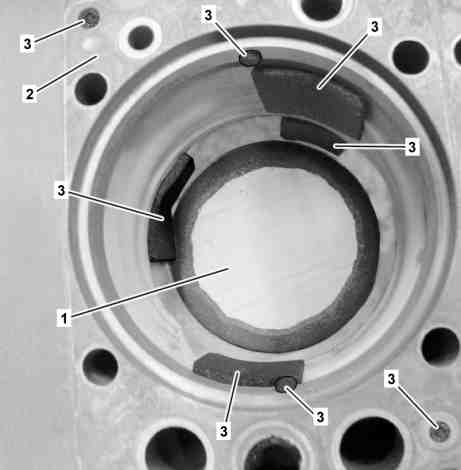
W01.40-1129-12
1 Insert shop-made cap (1) into the upper groove on the O-ring in the cylinder crankcase (2).
2 Cut insulation (3) (part number A 000 682 09 09) to size with an appropriate oversize to fit the coolant openings.
3 Close off all side coolant openings in the cylinder crankcase (2) with the cut-to-size insulation (3).
4 Close off both engine oil bores on the upper contact surface of the cylinder crankcase (2) with the insulation (3).

W01.40-1130-11
5 Close off all coolant and tappet rod bores on the upper contact surface of the cylinder crankcase (2) using the shop-made stop plugs (4).

W01.40-1123-06
6 Insert rotatable blade (5) in the deburrer (6).
Use the respective rotatable blade (5) for the right or left hander.
7 Place rotatable blade (5) on the edge (arrow) of the bush neck and deburr the edge (arrow) using light pressure.
For a right hander turn counterclockwise or for a left hander turn clockwise.
8 Smoothen the deburred edge (arrow) using emery paper.

W01.40-1124-05
9 Remove chips from the bores in the cylinder crankcase (2) and on the cap (1) using a magnetic pin and suction out the bores.
10 Suction out bores for the cylinder head bolts in the cylinder crankcase (2).
11 Remove stop plugs (4), insulation (3) and caps (1).