07.2-114 Test routine 2 E-E carburetor system
A. Arrangement of components

N6 | Compressor cutoff control unit |
N15 | Kickdown cutoff relay |
N45 | 2 E-E carburetor control unit |
Y18 | Float chamber vent valve |
Y22/1 | Choke actuator |
Y22/2 | Throttle valve actuator |
B11/2 | Coolant temperature sensor (EZL/CIS-E/2 E-E) |
G3/2 | Heated oxygen sensor |
K1/1 | Overvoltage protection relay 87E, 7-pin |
K3 | Intake manifold heater relay |
R8 | Intake manifold heater |
R8/1 | 2 E-E carburetor heater |
R19 | 2 E-E resistance trimming plug |
R24 | Throttle valve potentiometer |
B. Testers, tools
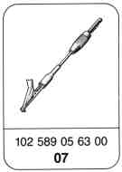
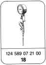
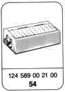
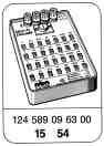
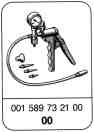
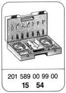
Special tools
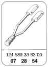
Commercial testers
Multimeter | e. g. Sun, DMM-5 |
Engine tester | e. g. Bosch, MOT 002.02 |
Lambda control tester | e. g. Hermann, L 115 |
Engine revolution counter | |
C. Connection diagram for testers

002 | Test cable |
003 | Multimeter |
004 | Contact box |
012 | Lambda control tester |
N45 | 2 E-E carburetor control unit |
N45x1 | Plug connection, 2 E-E carburetor control unit (wiring harness) |
X11 | Diagnostic socket 9-pin |
Symbols for testers
Contact box
Lambda control tester
Multimeter
Jumper
Contact
Pin
Symbols for quantities measured with multimeter:
Voltage measurement (Volts, direct voltage)
Current measurement (Amperes, direct current)
Resistance measurement (Ohms)
D. Contact assignment of control unit connector
Abbreviated designations
VDS = Choke actuator
DKA = Throttle valve actuator
DK-Poti = Throttle valve potentiometer

Contact
1 Terminal 30a (battery+, permanent voltage)
2 Engine ground (W11)
3 DKA contact 8 (+) air admission valve
4, 5 Not assigned
6 Idle detection signal for ignition control unit (EZL)
7 DKA contact 4, DK-poti contact 3
Ground supply potis), resistance trimming plug
ground
8 Oxygen sensor signal
9 DKA contact 3 (+) evacuation valve
10 VDS contact 1 (+)
11 DK-poti contact 1 (poti wiper contact)
12 VDS contact 2 (-)
13 Terminal 15 (ignition)
14 Relay control (K3) intake manifold heater
(bypass heater)
15 DKA fault signal for ignition control unit (EZL)
16 Drive position cut-in signal (autom. transmission)
17 DKA contact 7 (poti wiper contact)
18 DKA contact 5, DK-poti contact 2 (voltage supply)
19 Air conditioning compressor cut-in signal
20 Battery ground (W10)
21 Coolant temperature sensor
22 Resistance trimming plug (KAT or RÜF detection)
23 Lambda test signal (diagnostic socket contact 3)
24 Not assigned
25 TD signal (engine speed)
E. Preliminary conditions and test instructions
Preliminary
The work contained in operation no.
07-1100, "Testing, adjusting engine" must be performed as the test routine is based on this item.
Engine oil temperature approx. 80 °C.
Battery voltage 11 - 14 Volts.
Oxygen sensor operational.
Ignition system and mechanical components of engine in proper working order.
Instructions
Do not detach or plug in control unit connector when ignition is switched on or engine running (voltage peaks!).
Use only digital testers for testing voltage or current of electronic components, not a stroboscopic lamp (voltage peaks!).
When performing test steps involving switching on ignition and off again, wait
10 seconds between switching off and on to allow the computer in the control unit to reset.
After performing operation no. 07-1100 "Testing, adjusting engine", further necessary test steps can be performed as an addition according to the tables
a) Fault readout with on/off ratio
b) Troubleshooting table (complaint/
remedy).
F. Fault readout with on/off ratio, possible causes of faults,
remedy according to test table
On/off ratio readout (constant) | Possible cause of fault | Test table: Test step |
10% | Interrupt/short-circuit, control unit (N45) throttle valve potentiometer (R24). Interrupt/short-circuit throttle valve potentiometer (R24). | 1 3 |
20% | Interrupt/short-circuit control unit (N45) throttle valve actuator (Y22/2). Interrupt/short-circuit potentiometer of throttle valve actuator (Y22/2). Malfunction of throttle valve actuator (leak, valve jamming). | 1 5 |
30% | No coolant temperature signal. Interrupt/short-circuit control unit (N45) coolant temperature sensor (B11/2). No engine ground (W11) at control unit. | 1 2 |
50% | a) Cars without lambda control: no fault in area of monitored signals. | - |
b) Cars with lambda control: oxygen sensor not operational (too cold) or faulty. Interrupt oxygen sensor control unit (N45). | 1 8 | |
70% | No TD signal (engine speed). Interrupt/short-circuit ignition control unit (N1/2) control unit (N45). | 1 6 |
80% | a) Ground control line for relay (K3) of intake manifold heater control unit (N45) contact 14 has connection to battery positive (short-circuit). b) Throttle valve actuator: Short-circuit in cables for evacuation or air admission valve control unit (N45). Short-circuit of solenoid coils of valves. c) Cable of control unit (N45) contact 15 ignition control unit (N1/2) Pin 4 connection to battery positive. | 1 5 12 14 |
90% | Interruption/short-circuit resistance trimming plug (R19) control unit (N45). No resistance trimming plug. | 1 11 |
G. Troubleshooting table (complaint/remedy)
Note
The following requirements apply to using this test table:
Ignition system and mechanical components of engine in proper working order
All plug connections tightly located
Specified resistance trimming plugs for ignition and carburetor systems (KAT or ECE)
Engine starts poorly when cold
Engine cuts out after cold start
Poor warming-up (idling, transition, acceleration)
Poor transition, acceleration (warm)
Poor idling (warm)
Lambda control cannot be set
Poor output
High fuel consumption
Poor hot start
Note
The figures in parentheses indicate the test sequence.
Possible cause | Remedy acc. to test step | Op. no. |
Voltage and ground supply for control unit (N45) | 1 | 07-1725 |
Choke actuator (Y22/1) | 4 | 07-1735 |
Coolant temperature sensor (B11/2) | 2 | 07-1713 |
Throttle valve actuator (Y22/2) | 5 | 07-1738 |
Throttle valve potentiometer (R24) | 3 | 07-1731 |
Engine speed signal (TD) | 6 | 07-1726 |
Oxygen sensor signal, oxygen sensor faulty (short to ground) | 8 | 07-5206 |
Idle signal for EZL ignition control unit | 7 | 07-1726 |
Ground for control unit contact 16 (manual transmission) | 9 | 07-1728 |
Fuel drips out of pre-atomizer | 22 | - |
1 | 1 | 1 | 1 | 1 | 1 | 1 | 1 | 1 | |
3 | 3 | 4 | 2 | 7 | 6 | 5 | |||
2 | 4 | 3 | 4 | 5 | 5 | 3 | |||
6 | 5 | 4 | 4 | ||||||
4 | 7 | 5 | 3 | 8 | 6 | ||||
5 | 6 | 7 | 6 | 6 | 4 | 7 | |||
3 | 6 | ||||||||
8 | 3 | ||||||||
9 | 9 | 5 | |||||||
14 | 7 | 3 | |||||||
Note
The figures in parentheses indicate the test sequence.
Note
The following requirements apply to using this test table:
Ignition system and mechanical components of engine in proper working order
All plug connections tightly located
Specified resistance trimming plugs for ignition and carburetor systems (KAT or ECE)
Engine starts poorly when cold
Engine cuts out after cold start
Poor warming-up (idling, transition, acceleration)
Poor transition, acceleration (warm)
Poor idling (warm)
Lambda control cannot be set
Poor output
High fuel consumption
Poor hot start
8 | 4 | 2 | 2 | ||||||
2 | 2 | ||||||||
6 | 5 | 9 | |||||||
2 | 2 | ||||||||
3 | |||||||||
2 | |||||||||
11 | 9 | 9 | 13 | 9 | 10 | ||||
8 | |||||||||
10 | 8 | 7 | 11 | 8 | 4 | ||||
10 | |||||||||
12 | |||||||||
Possible cause | Remedy acc. to test step | Op. no. |
Float chamber vent | 13 | 07-1100 |
Intake manifold/bypass heater (R8, R8/1) | 12 | 07-1744 |
Intake air preheater | 15 | 07-1100 |
Intake system leaking | 16 | 07-1100 |
2nd carburetor stage not fully open | 17 | 07-1203/1206 |
Full throttle stop | 18 | 07-1100 |
Fuel nozzle blocked, mixture too lean | 19 | 07-6101 |
Fuel pump | 20 | 07-5701 |
Resistance trimming plug position (2 E-E carburetor) | 21 | 07-1725 |
Drive position cut-in signal (automatic transmission) | 9 | 07-1728 |
Air conditioning compressor cut-in signal | 10 | 07-1728 |
H. Facility at resistance trimming plug for correcting complaints
regarding engine running
a) KAT connector1) (KAT cars - closed-loop control mode)
Position | Function | Complaint |
1 | Basic setting | - |
2 | Lean mixture over entire performance map. | High fuel consumption. |
3 | Enriching, dynamic and static performance map, at engine speeds < 2000 rpm and coolant temperature < 18 °C. | Transition fault, jerking at engine speeds < 18 °C. |
4 | Enriching, dynamic and static performance map, over entire engine speed range and coolant temperature < 18 °C. | Transition fault, jerking over entire engine speed range at coolant temeprature |
5 | Enriching dynamic performance map < 2000 rpm over entire coolant temperature range. Enriching static performance map at engine speed < 2000 rpm and coolant temperature up to 60 °C (only if engine started at coolant temperature < 18 °C). | Transition fault, at engine speed < 2000 rpm over entire coolant temperature range. Jerking at engine speed < 2000 rpm and coolant temperature up to 60 °C (only if engine started at coolant temperature |
6 | Enriching over entire dynamic performance map. Enriching over entire stationary performance map up to 60 °C coolant temperature (only if engine started at coolant temperature < 18 °C). | Transition fault over entire coolant temperature range. Jerking up to 60 °C coolant temperature (only if engine started at coolant temperature < 18 °C). |
7 | Idle speed increase by 100 rpm. | - |
1) Re-fit security seal to resistance trimming plug after adjusting.
Resistance and voltage levels1) (KAT resistance trimming plug)
Resistance trimming plug position | Resistance (W) | Voltage (V) 0.1 |
1 | 953 | 2.81 |
2 | 1 270 | 3.16 |
3 | 1 620 | 3,43 |
4 | 2 260 | 3.77 |
5 | 3 320 | 4,10 |
6 | 5 360 | 4.40 |
7 | 11 500 | 4.72 |
1) Measured with contact box between contacts 7 and 22. Detach control unit when measuring resistance.
Switch on ignition when measuring voltage.
b) ECE connector1) (RÜF cars - open-loop control mode)
Position | Function | Complaint |
1 | Basic setting | |
2 | Lean mixture over entire performance map | High fuel consumption |
3-6 Enriching dynamic and static performance map
3 | Enriching at engine speed < 2000 rpm and coolant temperature < 18 °C. | Transition fault, jerking at engine speed < 18 °C. |
4 | Enriching over entire engine speed range and coolant temperature < 18 °C. | Transition fault, jerking over entire engine speed range at coolant temperature |
5 | Enriching at engine speed < 2000 rpm over entire coolant temperature range. | Transition fault, jerking at engine speed |
6 | Enriching over entire dynamic and static performance map (at all engine speeds over entire coolant temperature range). | Transition fault, jerking over entire coolant temperature and engine speed range. |
7 | Idle speed increase by 100 rpm. | - |
1) Re-fit security seal to resistance trimming plug after adjusting.
Resistance and voltage levels1) (ECE resistance trimming plug)
Resistance trimming plug position | Resistance (W) | Voltage (V) 0.1 |
1 | 51 | 0.33 |
2 | 105 | 0.61 |
3 | 169 | 0.92 |
4 | 249 | 1.26 |
5 | 348 | 1.61 |
6 | 442 | 1.88 |
7 | 590 | 2.22 |
1) Measured with contact box between contacts 7 and 22. Detach control unit when measuring resistance.
Switch on ignition when measuring voltage.
I. Test table
Test step/ | Tester/ | Operation/ | Specification | Possible cause/ |
1 Voltage and ground supply of control unit (N45) | ||||
Ground supply a) Battery ground (W10) | N45 20 + | Ignition: OFF control unit (N45) disconnected. | 11-14 V | Battery ground (W10) loose, interrupt, contact fault. |
b) Engine ground (W11) | N45 2 + | Ignition: OFF control unit (N45) disconnected. | 11-14 V | Engine ground (W11) loose, interrupt, contact fault. |
c) Ground for: Throttle valve potentiometer (R24) Throttle valve potentiometer (Y22/2) Resistance trimming plug (R19) Screening O2 sensor cable | N45 7 + | Control unit (N45) connected. | 11-14 V | Control unit (N45) |
d) Test ground under load | N45 2 20 | Detach coolant temperature sensor connector (B11/2), connect with 2.5 kW test resistor and connect to ground (simulate Range mV Ignition: ON | < 0,05 V | Battery ground (W10) or engine ground (W11) loose, interrupt, Control unit (N45) |
Test step/ | Tester/ | Operation/ | Specification | Possible cause/ |
Voltage supply a) Continuous positive | N45 2 1 | 11-14 V | Overvoltage protection fuse (K1/1) faulty, overvoltage protection relay (K1/1) missing, faulty or contact fault, interrupt: Battery (G1) battery terminal block (X35) overvoltage protection relay (K1/1), contact 1. (See wiring diagram for contact assignment up to 08/86 ). | |
b) Ignition | N45 2 13 | Ignition: ON | 11-14 V | Overvoltage protection relay (K1/1) faulty, contact fault. Interrupt: Ignition Note Up to 08/86 terminal 15 for control unit (N45) was protected through fuse in fuse box (F1). Model 124 No. 11, Model 201, No. 2. (See wiring diagram for contact assignment.) |
Test step/ | Tester/ | Operation/ | Specification | Possible cause/ |
2 Coolant temperature sensor (B11/2) | N45 2 21 | Control unit (N45) connected. Ignition: ON, engine at operating temperature (approx. 85 °C coolant temperature). | 0.45-0.55 V | Interrupt/short-circuit control unit (N45) contact 21 temperature sensor (B11/2). Control unit (N45) |
Resistance | N45 2 21 | Ignition: ON, control unit (N45) disconnected. Engine at operating (approx. 85 °C coolant temperature). | 230-300 W | If wiring in order, test resistance; renew coolant temperature sensor (B11/2), if necessary. |
Voltage and resistance levels1)
Coolant temperature °C | Resistance (W) | Voltage (V) |
- 20 - 10 0 + 10 + 20 + 30 + 40 + 50 + 60 + 70 + 80 + 90 | 15 670 9 450 5 890 3 790 2 500 1 692 1 170 826 594 434 322 243 | 4.1 - 4.5 3.7 - 4.1 3.3 - 3.7 2.8 - 3.3 2.3 - 2.8 1.8 - 2.3 1.4 - 1.8 1.1 - 1.4 0.8 - 1.1 0.7 - 0.8 0.5 - 0.6 0.4 - 0.5 |
1) Measured with contact box between contact 2 and 21. Detach control unit when measuring resistance. Switch on ignition when measuring voltage.
Test step/ | Tester/ | Operation/ | Specification | Possible cause/ |
3 Throttle valve potentiometer (R24) | ||||
a) Voltage supply | N45 7 18 | Control unit (N45) connected. Ignition: ON | 4.6-5.1 V | Interrupt/short-circuit (N45) contact 18 throttle valve potentiometer (R24) Interrupt control unit (N45) contact 7 throttle valve potentiometer (R24) Control unit (N45) |
b) Potentiometer range | N45 7 11 | Ignition: OFF, after 10 seconds ignition: ON (plunger of throttle valve actuator fully extended). Slowly apply full throttle. | 1.0-1.5 V Voltage should rise up to | Interrupt/short-circuit (N45) contact 11 throttle valve potentiometer (R24) Interrupt control unit (N45) contact 7 throttle valve potentiometer (R24) |
c) Potentiometer resistance: Total resistance | N45 7 18 | Ignition: OFF, control unit (N45) and throttle valve actuator connector detached. (Throttle valve actuator plunger fully extended). | 1.4-2.6 kW | If wiring in order, test resistances of throttle valve potentiometer, replace throttle valve potentiometer if necessary. |
Wiper contact resistance in adjustment range | N45 7 11 | As above, then apply full throttle. | > 500 W 1.4-2.6 kW | |
Test step/ | Tester/ | Operation/ | Specification | Possible cause/ |
4 Choke actuator (Y22/1) | N45 12 10 | Control unit (N45) and throttle valve actuator connector attached. Choke moves easily. Ignition: ON, engine at operating temperature. | 0.2-0.5 V | Interrupt/short-circuit control unit (N45) contact 10 choke actuator connector (contact 1). Interrupt control unit (N45) contact 12 choke actuator connector (contact 2). Test coolant temperature sensor (B11/2) (test step 2). |
N45 12 10 | Ignition: OFF install 2.5kW test resistor. After 10 seconds ignition: ON, | 1.8-2.2 V with maximum choke gap 1.5 mm (measured at top vane). | If wiring and coolant temperature sensor are in order and variation from specification exists, test coil resistance of choke actuator (Y22/1). | |
Coil resistance | N45 12 10 | Ignition: OFF control unit (N45) disconnected. | 1.2-1.8 W | Renew choke actuator (Y22/1). |
5 Throttle valve actuator (Y22/2) Switching noise from evacuating valve | N45 1 9 | Ignition: OFF control unit (N45) disconnected. | Valve switching noise must be audible each time connection is made. | Interrupt/short-circuit control unit (N45) contact 9 or 3 throttle valve actuator (Y22/2) contact 3 or 8. |
Switching noise from air admission valve | N45 1 3 | Interrupt and re-establish connection several times. | If wiring in order, test coil resistance. | |
Coil resistance of evacuation valve | N45 2 9 | Ignition: OFF, control unit (N45) disconnected. | 25-40 W | Replace throttle valve actuator (Y22/2). |
Test step/ | Tester/ | Operation/ | Specification | Possible cause/ |
Coil resistance of air admission valve | N45 2 3 | Ignition: OFF, control unit (N45) disconnected. | 25-40 W | Renew throttle valve actuator (Y22/2). |
Control of evacuation valve | N45 2 9 | Control unit (N45) connected. Engine idling, then switch off. | When switching off for approx. | Control unit (N45) |
Control of air admission valve | N45 2 3 | Engine idling, then switch off. | When switching off after approx. 3 seconds for approx. | Control unit (N45) |
Throttle valve actuator potentiometer a) Voltage supply | N45 7 18 | Control unit (N45) connected. Ignition: ON | 4.6-5.1 V | Interrupt/short circuit control unit (N45) contact 18 throttle valve actuator potentiometer contact 5. Interrupt control unit (N45) contact 7 throttle valve actuator potentiometer contact 4. Control unit (N45) |
b) Potentiometer range | N45 7 17 | Control unit (N45) connected. Engine idling, then switch off. | approx. | No passage in air admission line for throttle valve actuator. Interrupt/short-circuit control unit (N45) contact 17 throttle valve actuator contact 7or control unit (N45) contact 7 throttle valve actuator contact 4. |
Test step/ | Tester/ | Operation/ | Specification | Possible cause/ |
Potentiometer resistances: Total resistance | N45 7 18 | Ignition: OFF Control unit (N45) and throttle valve potentiometer connector detached. | 1.4-2.6 kW | If wiring in order, replace throttle valve actuator (Y22/2). |
Wiper contact resistance in adjusting range | N45 7 17 | As before (throttle valve actuator plunger fully extended). | 1.2-2.4 kW | Throttle valve actuator (Y22/2) leaking (valves, diaphragm), renew if necessary. |
Leaktightness of evacuation valve | N45 7 17 | Control unit (N45) disconnected. Throttle valve potentiometer connector attached, start engine. (Fast running) | Reading from previous test must drop maximum 200 W within one minute. | |
Leaktightness of air admission valve | N45 1 9 | Control unit (N45) disconnected. Run engine until throttle valve actuator plunger is retracted, separate electrical connection contacts 19. | < 400 W Reading must rise maximum 200 W within one minute. | |
N45 7 17 | ||||
Test step/ | Tester/ | Operation/ | Specification | Possible cause/ |
Ease of movement of plunger of throttle valve actuator | Control unit (N45) connected. Run engine. Switch off engine and at the same time check plunger of throttle valve actuator. | Actuator must retract fully for approx. | Insufficient or no passage in air admission line for throttle valve actuator (Y22/2). Throttle valve actuator (Y22/2) faulty. | |
6 TD signal | N45 2 25 | Control unit (N45) connected. Engine idling, then increase engine speed. | 12-2 V (dropping as engine speed rises). | Interrupt/short-circuit of ignition control unit (N1/2) diagnostic socket terminal block terminal TD . a) manual transmission Compressor cutout control unit (N6) (only if A/C fitted) Control unit (N45) contact 25. b) automatic transmission Kickdown cutout relay (N15) compressor cutout control unit (N6) (only if A/C fitted) control unit (N45) contact 25. |
Test step/ | Tester/ | Operation/ | Specification | Possible cause/ |
7 Idle signal for EZL ignition control unit (N1/2) | N45 2 6 | Control unit (N45) connected, engine idling. | <0.6 V | Basic setting of throttle valve actuator incorrect. |
Partial throttle approx. | 10-14 V | Check throttle valve potentiometer and potentiometer of throttle valve actuator. Interrupt/short-circuit (N45) contact 6 ignition control unit (N1/2). | ||
8 O2 sensor | N45 7 8 | Control unit (N45) connected. Engine and O2 sensor at operating temperature. | ||
a) Sensor signal | Press choke open far enough for engine to still run (leaner mixture). | approx. | O2 sensor (G3/2) not operational (too cold), O2 sensor heater faulty. | |
Engine idling; press choke closed far enough for engine to still run (richer mixture). | approx. | Interrupt/short-circuit If smaller specified level is not reached, check whether idle mixture is not set too rich or if carburetor slightly flooded (e. g.: drips from pre-atomizer). If wiring in order and specified valvues not reached, renew O2 sensor (G3/2). | ||
Test step/ | Tester/ | Operation/ | Specification | Possible cause/ |
b) O2 sensor heater | G3/2x1 between positive cable | Ignition: ON Do not take reading until stable. | 0.8-1.3 A | Overvoltage protection relay (K1/1) faulty, contact fault. Interrupt/short-circuit (K1/1) contact 6 O2 sensor faulty. Note Up to 08/86 O2 sensor heater was protected by fuse in fuse box. Model 124 no. 11, Model 201 no. 2. |
9 Drive position cut-in signal (automatic transmission) | N45 2 16 | Control unit (N45) connected. Ignition: ON, selector lever position P and N. all drive positions | 0 V 5.0 V as from control unit part no. 006 545 51 32 11-12 V | Interrupt/short-circuit starter (M1) W124 Plug connection, starter wiring harness (X27) starter lockout switch (16/1) ignition starting switch (S2/1) engine plug connection (X26) control unit (N45) contact 16. W201 Plug connection term. 50 electrical centre (F1) starter lockout switch (S16/1) ignition starting switch (S2/1) plug connection, engine wiring harness (X26/3) control unit (N45) contact 16. |
Ground supply contact 16 control unit (N45) (manual transmission) | N45 16 1 | - | 11-14 V | Interrupt in ground cable. |
Test step/ | Tester/ | Operation/ | Specification | Possible cause/ |
10 Air conditioner compressor cut-in signal | N45 2 19 | Engine idling. Electromagn. clutch for air conditioning compressor engaged. | 11-14 V | Interrupt/short-circuit control unit compressor cutout (N6) (terminal 87z) control unit (N45) contact 19. |
11 Resistance trimming plug (R19) | N45 7 22 | Ignition: OFF. Control unit (N45) disconnected. Plug position "1" KAT ECE |
953 W 51 W | No resistance trimming plug (R19). Interrup/ short circuit in resistance trimming plug control unit (N45) contact 7 or 22. |
12 Intake manifold and bypass heater a) Relay control (K3) | N45 2 R8 | Control unit (N45) connected. 2.5 kW test resistor installed. | 11-14 V | Interrupt/short-circuit overvoltage protection (K1/1) contact 6 intake manifold heater relay (K3) contact 4. |
N45 2 R8/1 | Run engine. (Remove test resistor after testing). | 11-14 V | Relay (K3) contact 1 carburetor heater (R8/1) or intake manifold heater (R8). Connection to control unit positive (N45) contact 14 relay (K3) contact 5. Relay (K3) or control unit (N45) faulty. | |
Test step/ | Tester/ | Operation/ | Specification | Possible cause/ |
Current consumption of intake manifold heater | K3 K3 1 3 | Engine at operating temperature, control unit (N45) connected. Carburetor heater connector (R8/1) detached. Engine idling. Do not take reading of amperage until stable. | 7-13 A | Intake manifold heater (R8) faulty, renew if necessary. |
Current consumption of carburetor heater (R8/1) | K3 K3 1 3 | As before, but carburetor heater connector (R8/1) plugged in and intake manifold heater connector (R8) detached. | 1.5-3.0 A | Carburetor heater (R8/1) faulty; renew if necessary. |
13 Float chamber vent valve (Y18) | N45 2 Y18 | Control unit (N45) connected. Detach hose for float chamber vent at charcoal canister, suck at hose. | 11-14 V | |
Ignition: ON Ignition: OFF | No continuity Continuity | Interrupt/short-circuit overvoltage protection (K1/1) socket 6 intake manifold heater relay (K3) contact 4 float chamber vent valve connector (Y18). Float chamber vent valve (Y18) faulty. | ||
Test step/ | Tester/ | Operation/ | Specification | Possible cause/ |
14 Throttle valve actuator fault signal for ignition control unit EZL (N1/2) | N45 2 15 | Ignition: OFF Run engine at idling speed. | >3 V (dependent on ignition control unit version 4.6-5.1 V Firing point up to 12° after TDC. | Short-circuit control unit (N45) contact 15 ignition control unit EZL (N1/2) Connector 4. Ignition control unit or control unit (N45) faulty. |
N45 2 15 | Re-connect detached vacuum hose. | <0.7 V and firing point 11-15° BTDC. | Short-circuit control unit (N45) contact 15 ignition control unit EZL (N1/2). Connection to battery positive. Ignition control unit or control unit (N45) faulty. | |
15 Intake air preheater | Detach warm air hose at air filter. Check position of warm air flap (visual inspection). | |||
below approx. above approx. +30 °C. (ambient temperature) | Air flap closed. Air flap open. | Thermo control element for warm air flap faulty. | ||
Test step/ | Tester/ | Operation/ | Specification | Possible cause/ |
16 Leaktightness of intake system | Connect engine revolution counter and CO tester. | Engine idling Spray all sealing points with ISO-Octane DIN 51 756 or cleaning naphtha. | KAT Pointer of lambda control tester should not move to the left. Engine speed should not vary. RÜF Engine speed and CO reading should not vary. | Seal intake system. |
17 2nd carburetor stage (full opening) | Connect engine speed tester. | Apply full throttle. As soon as engine speed has risen to 4000 to 5000 rpm, hold both carburetor mixing chambers closed with your hands far enough for the engine to run at approx. | ||
Keep a check on actuating rod of 2nd stage vacuum cell. | Actuating rod should be retracted as far as the stop. | Check vacuum supply for 2nd stage vacuum cell and leaktightness (07.2-169). | ||
Test step/ | Tester/ | Operation/ | Specification | Possible cause/ |
18 Full throttle stop | Ignition: OFF. Depress accelerator pedal of manual transmission fully, of automatic transmission as far as the stop on the kickdown switch. | |||
Check throttle valve lever and full throttle stop at carburetor. | Throttle valve lever must be resting against full throttle stop. | Adjust full throttle stop (07.2-110). | ||
19 Carburetor nozzles | Remove carburetor cover, check that nozzle passage is clear and of correct size (visual inspection). | Passage clear and nozzle of specified size. | Blow fuel nozzles and passages clear with compressed air; replace fuel nozzles if necessary. | |
20 Fuel pump | Connect vacuum pressure gauge. | Suction side: Operate starter until vacuum no longer rises. | 330-600 mbar. Maximum permissible pressure drop in first minute | |
Pressure side: Operate starter until pressure no longer rises. | 0.20-0.40 bar (gauge pressure), maximum permissible pressure drop in first minute | Fuel pump faulty. | ||
Test step/ | Tester/ | Operation/ | Specification | Possible cause/ |
21 Setting 2 E-E resistance trimming plug (R19) to correct position | Visual inspection of setting of resistance trimming plug. | Basic setting KAT and RÜF position "1". | If necessary, re-set resistance trimming plug depending on complaint (07.2-114, Section H). | |
22 Carburetor flooding | Run engine until hot. | |||
Visual inspection of pre-atomizer of 1st and 2nd stage. | No fuel should flow out. | Check valve in fuel return line leaking or incorrectly installed. Passage of float chamber vent hose not clear. Hose should be at a downward slope. Float needle valve leaking, wrong float level. Float too heavy because leaking (flooded with fuel). | ||
J. Wiring diagrams

2 E-E carburetor system, Model 201 with manual transmission (with 5-pin overvoltage protection, up to August 1986)
X51 | Terminal block terminal 87 |
Y18 | Float chamber vent valve |
Y22/1 | Choke actuator |
Y22/2 | Throttle valve actuator |
Z | Connector sleeve terminal (solder joint in harness) |
a | Feed terminal 30 electrical centre |
|
Grounding point without designation: | |
Colour coding of wiring bl =blue | |
br =brown | |
el =ivory | |
ge =yellow | |
gn =green | |
gr =grey | |
nf =neutral | |
rs =pink | |
rt =red | |
sw =black | |
vi =purple | |
ws =white |
B11/2 | Coolant temperature sensor (EZL/CIS-E/2 E-E) |
F1 | Fuse and relay box |
G3/2 | Heated oxygen sensor |
G3/2x1 | Plug connection, oxygen sensor heating coil |
G3/2x2 | Plug connection, oxygen sensor signal |
K1 | Overvoltage protection relay, 5-pin |
K3 | Intake manifold heater relay |
N1/2 | EZL control unit |
N6 | A/C compressor cutoff control unit |
N45 | 2 E-E carburetor control unit |
R8 | Intake manifold heater |
R8/1 | 2 E-E carburetor heater |
R19 | 2 E-E resistance trimming plug |
R24 | Throttle valve potentiometer |
W3 | Ground, front left wheelhouse (ignition coil) |
W9 | Ground, front left (next to headlamp unit) |
W10 | Ground, battery |
W11 | Ground, engine (electric cable screwed on) |
X11 | Diagnostic socket/terminal block terminal TD |
X35 | Terminal block terminal 30/terminal 61 |

2 E-E carburetor system, Model 201 with manual transmission (7- or 9-pin overvoltage protection, from September 1986)
X11 | Diagnostic socket/terminal block terminal TD |
X14 | Plug connection, terminal 50 |
X26/1 | Plug connection, engine wiring harness/headlamp wiring harness, 1-pin diagnosis |
X35 | Terminal block terminal 30/terminal 61 |
X48 | Solder joint in wiring harness |
Y18 | Float chamber vent valve |
Y22/1 | Choke actuator |
Y22/2 | Throttle valve actuator |
Grounding point without designation: | |
Colour coding of wiring bl =blue br =brown el =ivory ge =yellow gn =green gr =grey nf =neutral rs =pink rt =red sw =black vi =purple ws =white |
B11/2 | Coolant temperature sensor (EZL/CIS-E/2 E-E) |
F1 | Fuse and relay box |
G1 | Battery |
G3/2 | Heated oxygen sensor |
G3/2x1 | Plug connection, oxygen sensor heating coil |
G3/2x2 | Plug connection, oxygen sensor signal |
K1/1 | Overvoltage protection relay, 87E, 7-pin |
K3 | Intake manifold heater relay |
M1 | Starter |
N1/2 | EZL control unit |
N6 | A/C compressor cutoof control unit |
N45 | 2 E-E carburetor control unit |
R8 | Intake manifold heater |
R8/1 | 2 E-E carburetor heater |
R19 | 2 E-E resistance trimming plug |
R24 | Throttle valve potentiometer |
S2/1 | Ignition starter switch |
W3 | Ground, wheelhouse front left (ignition coil) |
W9 | Ground, front left (next to headlamp unit) |
W10 | Ground, battery |
W11 | Ground, engine (electric cable screwed on) |

2 E-E carburetor system, Model 201 with manual transmission (7- or 9-pin overvoltge protection, from September 1988)
B11/2 | Coolant temperture sensor (EZL/CIS-E/2 E-E) |
F1 | Fuse and relay box |
G1 | Battery |
G3/2 | Heated oxygen sensor |
G3/2x1 | Plug connection, oxygen sensor heating coil |
G3/2x2 | Plug connection, oxygen sensor signal |
K1/1 | Overvoltage protection relay 87E, 7-pin |
K3 | Intake manifold heater relay |
M1 | Starter |
N1/2 | EZL control unit |
N6 | A/C compressor cutout control unit |
N45 | 2 E-E carburetor control unit |
R8 | Intake manifold heater |
R8/1 | 2 E-E carburetor heater |
R19 | 2 E-E resistance trimming plug |
R24 | Throttle valve potentiometer |
S2/1 | Ignition starter switch |
W3 | Ground, wheelhouse front left (ignition coil) |
W9 | Ground, front left (next to headlamp unit) |
W10 | Ground, battery |
W11 | Ground, engine (electric cable screwed on) |
X11 | Diagnostic socket/terminal block, terminal TD |
X14 | Plug connection, terminal 50 |
X26/1 | Plug connection, engine wiring harness/headlamp wiring harness, 1-pin, diagnosis |
X35 | Terminal block, terminal 30/terminal 61 |
Y18 | Float chamber vent valve |
Y22/1 | Choke actuator |
Y22/2 | Throttle valve actuator |
Z | Connector sleeve (solder joint in harness) |
Grounding point without designation: | |
Colour coding of wiring bl =blue br =brown el =ivory ge =yellow gn =green gr =grey nf =neutral rs =pink rt =red sw =black vi =purple ws =white |

2 E-E carburetor system, Model 201 with automatic transmission (with 5-pin overvoltage protection, up to August 1986)
Y18 | Float chamber vent valve |
Y22/1 | Choke actuator |
Y22/2 | Throttle valve actuator |
Z | Connector sleeve (solder joint in harness) |
a | Feed terminal 30 electrical centre |
b | Starter lockout switch, terminal 50 |
c | Kickdown switch |
d | Feed, terminal 30 electrical centre |
Grounding point without designation: | |
Colour coding of wiring bl =blue br =brown el =ivory ge =yellow gn =green gr =grey nf =neutral rs =pink rt =red sw =black vi =purple ws =white |
B11/2 | Coolant temperature sensor (EZL/CIS-E/2 E-E) |
F1 | Fuse and relay box |
G3/2 | Heated oxygen sensor |
G3/2x1 | Plug connection, oxygen sensor heating coil |
G3/2x2 | Plug connection, oxygen sensor signal |
K1 | Overvoltage protection relay, 5-pin |
K3 | Intake manifold heater relay |
N1/2 | EZL control unit |
N6 | A/C compressor cutout control unit |
N15 | Kickdown cutout relay |
N45 | 2 E-E carburetor control unit |
R8 | Intake manifold heater |
R8/1 | 2 E-E carburetor heater |
R19 | 2 E-E resistance trimming plug |
R24 | Throttle valve potentiometer |
W3 | Ground, front left wheelhouse (ignition coil) |
W9 | Ground, front left (next to headlamp unit) |
W10 | Ground, battery |
W11 | Ground, engine (electric cable screwed on) |
X11 | Diagnostic socket/terminal block terminal TD |
X35 | Terminal block terminal 30/terminal 61 |
X51 | Terminal block terminal 87 |

2 E-E carburetor system, Model 201 with automatic transmission (with 7- or 9-pin overvoltage protection, from September 1986)
S2/1 | Ignition starter switch |
S15 | Economy mode switch (---S16/5---) |
S16/1 | Starter lockout and backup light switch |
S30/2 | Economy mode kickdown switch |
W3 | Ground, wheelhouse front left (ignition coil) |
W6 | Ground, left wheelhouse in trunk |
W9 | Ground, front left (next to headlamp unit) |
W10 | Ground, battery |
W11 | Ground engine (electric cable screwed on) |
X11 | Diagnostic socket/terminal block terminal TD |
X14 | Plug connection terminal 50 |
X26/1 | Plug connection, engine wiring harness/headlamp wiring harness, 1-pin, diagnosis |
X26/3 | Plug connection, engine wiring harness/tail lamp wiring harness, 2-pin |
X35 | Terminal block terminal 30/terminal 61 |
Y3 | Automatic transmission switchover valve |
Y4 | Economy mode switchover valve |
Y18 | Float chamber vent valve |
B11/2 | Coolant temperature sensor (EZL/CIS-E/2 E-E) |
F1 | Fuse and relay box |
G1 | Battery |
G3/2 | Heated oxygen sensor |
G3/2x1 | Plug connection, heating coil |
G3/2x2 | Plug connection, oxygen sensor signal |
K1/1 | Overvoltage protection relay 87E, 7-pin |
K3 | Intake manifold heater relay |
M1 | Starter |
N1/2 | EZL control unit |
N6 | A/C compressor cutout control unit |
N15 | Kickdown cutout relay |
N45 | 2 E-E carburetor control unit |
R8 | Intake manifold heater |
R8/1 | 2 E-E carburetor heater |
R19 | 2 E-E resistance trimming plug |
R24 | Throttle valve potentiometer |
Y22/1 | Choke actuator |
Y22/2 | Throttle valve actuator |
Z | Connector sleeve (solder joint in harness) |
|
Grounding point without designation: |
Colour coding of wiring bl =blue br =brown el =ivory ge =yellow gn =green gr =grey nf =neutral rs =pink rt =red sw =black vi =purple ws =white |

2 E-E carburetor system, Model 201 with automatic transmission (with 7- or 9-pin overvoltage protection, as from September 1988)
S2/1 | Ignition starter switch |
S15 | Economy mode switch (---S16/5---) |
S16/1 | Starter lockout and backup light switch |
S30/2 | Economy mode kickdown switch |
W3 | Ground, wheelhouse front left (ignition coil) |
W6 | Ground, left wheelhouse in trunk |
W9 | Ground, front left (next to headlamp unit) |
W10 | Ground, battery |
W11 | Ground, engine (electric cable screwed on) |
X11 | Diagnostic socket/terminal block terminal TD |
X14 | Plug connection, terminal 50 |
X26/1 | Plug connection, engine wiring harness/headlamp wiring harness, 1-pin diagnosis |
X26/3 | Plug connection, engine wiring harness/headlamp wiring harness, 2-pin |
X35 | Terminal block terminal 30/terminal 61 |
B11/2 | Coolant temperature sensor (EZL/CIS-E/2 E-E) |
F1 | Fuse and relay box |
G1 | Battery |
G3/2 | Heated oxygen sensor |
G3/2x1 | Plug connection, oxygen sensor heating coil |
G3/2x2 | Plug connection, oxygen sensor signal |
K1/1 | Overvoltage protection relay 87E, 7-pin |
K3 | Intake manifold heater relay |
M1 | Starter |
N1/2 | EZL control unit |
N6 | A/C compressor cutout control unit |
N45 | 2 E-E carburetor control unit |
R8 | Intake manifold heater |
R8/1 | 2 E-E carburetor heater |
R19 | 2 E-E resistance trimming plug |
R24 | Throttle valve potentiometer |
Y3 | Automatic transmission switchover valve |
Y4 | Economy mode switchover valve |
Y18 | Float chamber vent valve |
Y22/1 | Choke actuator |
Y22/2 | Throttle valve actuator |
Z | Connector sleeve (solder joint in harness) |
Grounding point without designation: |
Colour coding of wiring bl =blue br =brown el =ivory ge =yellow gn =green gr =grey nf =neutral rs =pink rt =red sw =black vi =purple ws =white |

2 E-E carburetor system, Model 124 with manual transmission (with 5-pin overvoltage protection up to August 1986)
Y22/1 | Choke actuator |
Y22/2 | Throttle valve actuator |
Z | Connector sleeve (solder joint in harness) |
a | Fuse no. 11 |
b | Fuse no. 7 (terminal 15 unprotected) |
c | Ignition starter switch, terminal 50 |
Grounding point without designation: | |
Colour coding of wiring bl =blue br =brown el =ivory ge =yellow gn =green gr =grey nf =neutral rs =pink rt =red sw =black vi =purple ws =white |
B11/2 | Coolant temperature sensor (EZL/CIS-E/2 E-E) |
G3/2 | Heated oxygen sensor |
G3/2x1 | Plug connection, oxygen sensor heating coil |
G3/2x2 | Plug connection, oxygen sensor signal |
K1 | Overvoltage protection relay, 5-pin |
K3 | Intake manifold heater relay |
N1/2 | EZL control unit |
N6 | A/C compressor cutout control unit |
N45 | 2 E-E carburetor control unit |
R8 | Intake manifold heater |
R8/1 | 2 E-E carburetor heater |
R19 | 2 E-E resistance trimming plug |
R24 | Throttle valve potentiometer |
W3 | Ground, wheelhouse front left (ignition coil) |
W10 | Ground, battery |
W11 | Ground, engine (electric cable screwed on) |
X11 | Diagnostic socket/terminal block terminal TD |
X26 | Plug connection, interior/engine |
X35 | Terminal block terminal 30/terminal 61 |
X51 | Terminal block, terminal 87 |
Y18 | Float chamber vent valve |

2 E-E carburetor system, Model 124 with manual transmission (with 7- or 9-pin overvoltage protection, as from September 1986)
X4 | Terminal block, terminal 30, fuse and |
X11 | Diagnostic socket/terminal block terminal TD |
X26 | Plug connection, interior/engine |
X27 | Plug connection, starter wiring harness |
X35 | Terminal block terminal 30/terminal 61 |
X49/1 | Plug connection, backup light switch |
B11/2 | Coolant temperature sensor (EZL/CIS-E/2 E-E) |
F1 | Fuse and relay box |
G1 | Battery |
G3/2 | Heated oxygen sensor |
G3/2x1 | Plug connection, oxygen sensor heating coil |
G3/2x2 | Plug connection, oxygen sensor signal |
K1/1 | Overvoltage protection relay 87E, 7-pin |
K3 | Intake manifold heater relay |
M1 | Starter |
N1/2 | EZL control unit |
N6 | A/C compressor cutout control unit |
N45 | 2 E-E carburetor control unit |
R8 | Intake manifold heater |
R8/1 | 2 E-E carburetor heater |
R19 | 2 E-E resistance trimming plug |
R24 | Throttle valve potentiometer |
S2/1 | Ignition starting switch |
W3 | Ground, wheelhouse front left (ignition coil) |
W9 | Ground, front left (next to headlamp unit) |
W10 | Ground, battery |
W11 | Ground, engine (electric cable screwed on) |
Y18 | Float chamber vent valve |
Y22/1 | Choke actuator |
Y22/2 | Throttle valve actuator |
Z | Connector sleeve (solder joint in harness) |
Grounding point without designation: |
Colour coding of wiring bl =blue br =brown el =ivory ge =yellow gn =green gr =grey nf =neutral rs =pink rt =red sw =black vi =purple ws =white |

2 E-E carburetor system, Model 124 with manual transmission (with 7- or 9-pin overvoltage protection, as from September 1988)
X4 | Terminal block, terminal 30, fuse and relay box |
X11 | Diagnostic socket/terminal block terminal TD |
X26 | Plug connection, interior/engine |
X27 | Plug connection, starter wiring harness |
X35 | Terminal block terminal 30/terminal 61 |
X49/1 | Plug connection, backup light switch |
Y18 | Float chamber vent valve |
Y22/1 | Choke actuator |
Y22/2 | Throttle valve actuator |
Z | Connector sleeve (solder joint in harness) |
Grounding point without designation: |
B11/2 | Coolant temperature sensor (EZL/CIS-E/2 E-E) |
F1 | Fuse and relay box |
G1 | Battery |
G3/2 | Heated oxygen sensor |
G3/2x1 | Plug connection, oxygen sensor heating coil |
G3/2x2 | Plug connection, oxygen sensor signal |
K1/1 | Overvoltage protection relay 87E, 7-pin |
K3 | Intake manifold heater relay |
M1 | Starter |
N1/2 | EZL control unit |
N6 | A/C compressor cutout control unit |
N45 | 2 E-E carburetor control unit |
R8 | Intake manifold heater |
R8/1 | 2 E-E carburetor heater |
R19 | 2 E-E resistance trimming plug |
R24 | Throttle valve potentiometer |
S2/1 | Ignition starter switch |
W3 | Ground, wheelhouse front left (ignition coil) |
W9 | Ground, front left (next to headlamp unit) |
W10 | Ground, battery |
W11 | Ground, engine (electric cable screwed on) |
Colour coding of wiring bl =blue br =brown el =ivory ge =yellow gn =green gr =grey nf =neutral rs =pink rt =red sw =black vi =purple ws =white |

2 E-E carburetor system, Model 124 with automatic transmission (with 5-pin overvoltage protection, up to August 1986)
Y18 | Float chamber vent valve |
Y22/1 | Choke actuator |
Y22/2 | Throttle valve actuator |
Z | Connector sleeve (solder joint in harness) |
a | Fuse no. 11 |
b | Fuse no. 7 (terminal 15 unprotected) |
c | Ignition starter switch, terminal 50 |
d | Kickdown switch |
Grounding point without designation: | |
Colour coding of wiring bl =blue br =brown el =ivory ge =yellow gn =green gr =grey nf =neutral rs =pink rt =red sw =black vi =purple ws =white |
B11/2 | Coolant temperature sensor (EZL/CIS-E/2 E-E) |
G3/2 | Heated oxygen sensor |
G3/2x1 | Plug connection, oxygen sensor heating coil |
G3/2x2 | Plug connection, oxygen sensor signal |
K1 | Overvoltage protection relay, 5-pin |
K3 | Intake manifold heater relay |
N1/2 | EZL control unit |
N6 | A/C compressor cutout control unit |
N15 | Kickdown cutout control unit |
N45 | 2 E-E carburetor control unit |
R8 | Intake manifold heater |
R8/1 | 2 E-E carburetor heater |
R19 | 2 E-E resistance trimming plug |
R24 | Throttle valve potentiometer |
W3 | Ground, wheelhouse front left (ignition coil) |
W10 | Ground, battery |
W11 | Ground, engine (electric cable screwed on) |
X11 | Diagnostic socket/terminal block terminal TD |
X26 | Plug connection, interior/engine |
X35 | Terminal block terminal 30/terminal 61 |
X51 | Terminal block, terminal 87 |

2 E-E carburetor system, Model 124 with automatic transmission (with 7- or 9-pin overvoltage protection, as from September 1986)
X4 | Terminal block, terminal 30, fuse and relay box |
X11 | Diagnostic socket/terminal block terminal TD |
X26 | Plug connection, interior/engine |
X27 | Plug connection, starter wiring harness |
X35 | Terminal block, terminal 30/terminal 61 |
Y3 | Automatic transmission switch-over valve |
Y4 | Economy mode switch-over valve |
Y18 | Float chamber vent valve |
Y22/1 | Choke actuator |
Y22/2 | Throttle valve actuator |
Z | Connector sleeve (solder joint in harness) |
Grounding point without designation: |
B11/2 | Coolant temperature sensor (EZL/CIS-E/2 E-E) |
F1 | Fuse and relay box |
G1 | Battery |
G3/2 | Heated oxygen sensor |
G3/2x1 | Plug connection, oxygen sensor heating coil |
G3/2x2 | Plug connection, oxygen sensor signal |
K1/1 | Overvoltage protection relay 87E, 7-pin |
K3 | Intake manifold heater relay |
M1 | Starter |
N1/2 | EZL control unit |
N6 | A/C compressor cutout control unit |
N15 | Kickdown cutout relay |
N45 | 2 E-E carburetor control unit |
R8 | Intake manifold heater |
R8/1 | 2 E-E carburetor heater |
R19 | 2 E-E resistance trimming plug |
R24 | Throttle valve potentiometer |
S2/1 | Ignition starter switch |
S15 | Economy mode switch (---S16/5---) |
S16/1 | Starter lockout and backup light switch |
S30/2 | Economy mode kickdown switch |
W3 | Ground, wheelhouse front left (ignition coil) |
W6 | Ground, left wheelhouse in trunk |
W9 | Ground, front left (next to headlamp unit) |
W10 | Ground, battery |
W11 | Ground, engine (electric cable screwed on) |
Colour coding of wiring bl =blue br =brown el =ivory ge =yellow gn =green gr =grey nf =neutral rs =pink rt =red sw =black vi =purple ws =white |

2 E-E carburetor system, model 124 with automatic transmission (with 7 or 9-pin overvoltage protection, as from September 1988)
X4 | Terminal block, terminal 30, fuse and |
X11 | Diagnostic socket/terminal block, terminal TD |
X26 | Plug connection, interior/engine |
X27 | Plug connection, starter wiring harness |
X35 | Terminal block, terminal 30/terminal 61 |
Y3 | Automatic transmission switch-over valve |
Y4 | Economy mode switch-over valve |
Y18 | Float chamber vent valve |
Y22/1 | Choke actuator |
Y22/2 | Throttle valve actuator |
Z | Connector sleeve (solder joint in harness) |
Grounding point without designation: |
B11/2 | Coolant temperature sensor (EZL/CIS-E/2 E-E) |
F1 | Fuse and relay box |
G1 | Battery |
G3/2 | Heated oxygen sensor |
G3/2x1 | Plug connection, oxygen sensor heating coil |
G3/2x2 | Plug connection, oxygen sensor signal |
K1/1 | Overvoltage protection relay 87E, 7-pin |
K3 | Intake manifold heater relay |
M1 | Starter |
N1/2 | EZL control unit |
N6 | A/C compressor cutout control unit |
N15 | Kickdown cutout relay |
N45 | 2 E-E carburetor control unit |
R8 | Intake manifold heater |
R8/1 | 2 E-E carburetor heater |
R19 | 2 E-E resistance trimming plug |
R24 | Throttle valve potentiometer |
S2/1 | Ignition starter switch |
S15 | Economy mode switch (---S16/5---) |
S16/1 | Starter lockout and backup light switch |
S30/2 | Economy mode kickdown switch |
W3 | Ground, wheelhouse front left (ignition coil) |
W6 | Ground, left wheelhouse in trunk |
W9 | Ground, front left (next to headlamp unit) |
W10 | Ground, battery |
W11 | Ground, engine (electric cable screwed on) |
Colour coding of wiring bl =blue br =brown el =ivory ge =yellow gn =green gr =grey nf =neutral rs =pink rt =red sw =black vi =purple ws =white |
K. Arrangement of grounding points, plug connections, terminal blocks, relays and electrical connections of components


W11 | Engine ground (electric cable screwed on) |
W10 | Battery ground |
X35 | Terminal block, terminal 30/61 (battery) |


W3 | Ground, wheelhouse front left (ignition coil) |
W9 | Ground, front left (next to headlamp unit) |


G3/2x1 | Plug connection, oxygen sensor heater |
G3/2x2 | Plug connection, oxygen sensor signal |
X26 | Plug connection, interior/engine (in fuse box) |


X4 | Terminal block, terminal 30, fuse and relay box |
R19 | 2 E-E carburetor resistance trimming plug |


K1/1 | Overvoltage protection relay |
N6 | A/C compressor cutout control unit |
N15 | Kickdown cutout relay |
N45 | 2 E-E carburetor control unit |
Arrow | Coolant temperature sensor |


Model 201 | |
K3 | Intake manifold heater relay |
Model 124 | |
K3 | Intake manifold heater relay |


Y22/1 | Choke actuator |
Y22/2 | Throttle valve actuator |


R24 | Throttle valve potentiometer |
R8/1 | 2 E-E carburetor heater |

R8 | Intake manifold heater |