07.2-110 Testing, adjusting engine
Operation no. of operation texts and work units or standard texts and flat rates 07-1100 |

Test sheet | complete. |
Testers (see ill.) | connect. |
Coolant level | check, adjust to correct level. |
Engine oil level | check, pay attention to condition of oil (visual inspection). |
Oil level in automatic transmission | check. |
Air filter | remove, install. |
Accelerator control | check ease of movement and condition, lubricate bearing points, relay levers, ball sockets. |
Full throttle stop | check from accelerator pedal lever, adjust. |
Battery no-load and starting voltage | check. |
Ignition coil: voltage (terms. 1 and 15) | test. |
Resistance trimming plug for 2 E-E carburetor | test pin assignment (KAT/RÜF). |
Engine oil temperature | raise to approx. 80 °C. |
Firing point, total vacuum |
check, adjust. |
Firing point with simulated throttle |
check. |
Oscilloscope image | analyse. |
Function test of 2 E-E carburetor | perform. |
2nd carburetor stage | test full opening. |
Float chamber vent valve | check. |
Output system | test for leaktightness by spraying. |
Intake air preheater | test, flap position (visual inspection). |
Idling speed | test. |
Lambda control (KAT) | test, adjust. |
Idle exhaust emissions level (RÜF) | test, adjust. |
Test and adjusting data
Firing point
Engine/ | Ignition control unit EZL part no. | Engine speed in rpm | Firing point in ° CA before TDC 1) | ||
Resistance trimming plug position | w/o vacuum | with vacuum | |||
102.922 | 004 545 79 32 | 3200 | S | 22-26 | 38-42 |
102.924 | 004 545 81 32 | N | 15-19 | ||
KAT/RÜF | 006 545 40 32 006 545 41 32 | Idling | S and N | 11-15 | 11-15 |
006 545 52 322) | 3200 | S | 19-23 | 38-42 | |
006 545 53 322) | N | 14-18 | |||
Idling | S and N | 11-15 | 11-15 | ||
1) If readout varies, test ignition system (15-540).
2) Ignition control unit with fault control in the event of throttle valve actuator faults.
Idle speed
Engine | Version | Idle speed in rpm | Idle exhaust emissions level % CO (RÜF) | Lambda control range % |
102.922 | RÜF | 700-800 | 1.50.5 | - |
102.924 | KAT | 1) | 5010 | |
1) For special exhaust emissions test (ASU) 0.5 %.
Battery voltages
No-load voltage | 12.2 Volts |
Starting voltage, minimum | 10 Volts |
Voltages at ignition coil (engine not running, ignition switched on)
Terminal 15 to ground | Battery voltage |
Between terminal 1 and terminal 15 | 0 Volts |
Choke actuator (VD)
Test condition: Coolant temperature +20 °C (simulated with test resistor) Ignition: On |
Choke gap |
max. 1.5 mm |

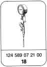
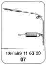

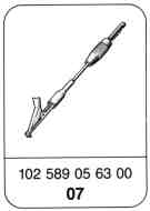
Special tools
Commercial testers
Revolution counter | |
Engine tester with oscilloscope | e. g. Bosch, |
Lambda control tester | e.g. Hermann, L 115 |
Multimeter | e.g. Sun, DMM-5 |
CO tester | |
Note
Do not detach crankcase breather for setting idle speed!
Idle speed must not be adjusted when engine is hot, e. g. immediately after driving car sharply or after measuring engine output on the performance tester.

Adjusting engine
1 Complete test sheet.
2 Connect testers:
Engine tester with oscilloscope
CO tester
Lambda control tester
Oil telethermometer
3 Check coolant level, adjust to correct level.
4 Check engine oil level, paying attention to condition of oil (visual inspection).
5 Check oil level in automatic transmission.
6 Switch off air conditioning or automatic climate control. Move selector lever into position "P".

7 Take off air filter.
Unscrew nut (arrow) before removing the air filter body.

8 Check ease of movement and condition of accelerator control linkage and throttle valve. Lubricate all bearing points and ball sockets.
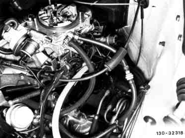
9 Check adjustment of accelerator linkage, correct. Retract throttle valve actuator plunger fully (decel fuel cutoff position!). This is done by detaching hose at air admission connection of throttle valve actuator. Run engine and switch off again.
Detach accelerator control rod (1) and ball head (2). The accelerator control lever should now be resting against the stop (arrow) and there should be no clearance at the driver compression spring. (If not, perform basic setting of accelerator control 30-300.)

If the accelerator control lever is resting against the stop, attach accelerator control rod (1) and adjust so that the idle travel (arrows) is approx. 0.2 mm.
1 Accelerator control rod,
1st version

If accelerator control rod 2nd version (flat rod) is fitted, adjust rod so that the hole in the rod is half-visible.
Accelerator control rod
2nd version
Adjusting full throttle stop
This is done by depressing the accelerator fully on cars fitted with manual transmission, and as far as the stop on the kickdown switch on cars with automatic transmission
(do not operate kickdown switch).
The throttle valve lever (27) must now be resting against full throttle stop (28); adjust Bowden cable with the adjusting screw (21), if necessary.
10 Check cruise control setting, adjust if necessary. Detach connecting rod (1) at carburetor with the plunger of the throttle valve actuator fully retracted. Press lever of actuator in direction of engine as far as the stop.
Now adjust connecting rod (1) so that the lever of the actuator must be pulled back approx.
1 mm from the engine for attaching.

Tempomat/cruise control
M16 Tempomat/cruise control actuator
1 Connecting rod
3 Ball head
Remove clip on the hose of the air admission valve of the throttle valve actuator.
11 Adjust control pressure Bowden cable (automatic transmission).
Run engine at idle speed when performing this step. Detach ball socket (2), push back fully, then pull forward again until a slight resistance is felt.
It must now be possible to attach the ball socket to the ball head free of tension; alter setting of adjusting screw (22), if necessary.
12 Test battery no-load and starting voltage.
a) Battery no-load voltage
Connect voltmeter to battery, paying attention to polarity, and take reading of voltage. Specification: 11 - 14 Volts.
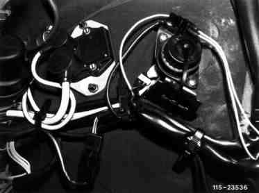
b) Battery starting voltage
Plug protective connector 102 589 02 21 00 to diagnostic socket, or detach connector for position sensor signal at ignition control unit.
Operate starter and take reading of voltage.
Specification: minimum 10 Volts.
Unplug protective connector.

13 Test voltages at ignition coil.
Engine not running. Switch on ignition. Test voltage, terminal 15 to ground at contact 5 of diagnostic socket (3).
Specification: battery voltage.
Test difference in voltage between terminal 15 and terminal 1 between contacts 4 and 5 of diagnostic socket (3).
Specification: 0 Volts.
(If reading varies from specification, additionally test ignition system 15-540).

14 Test resistance trimming plug (arrow) for
2 E-E carburetor.
KAT cars= Connector with inscription "KAT"
RÜF cars= Connector with inscription "ECE"
15 Raise engine oil temperature to approx.
80 °C.
16 Test firing point and total vacuum advance (15-515).

At the same time, also test firing point with simulated throttle valve actuator fault.
This is done by detaching vacuum hose at the evacuation port (92) of the throttle valve actuator with the ignition switched off. Run engine at idle speed and test firing point.
Specification: approx. 12° after TDC.
Re-fit vacuum hose with engine idling and test firing point.
Specification: 11 - 15° before TDC.
If variation from specification exists, additionally perform test step 14 (07.2-114, Section "I").
17 Analyze oscilloscope image (15-525).
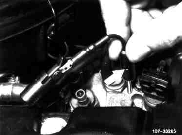
18 Perform function test of 2 E-E carburetor.
This is done by simulating +20 °C coolant temperature with ignition switched off, using a 2.5 kW test resistor.

Switch on ignition and check chocke gap (arrows).
Specification: max. 1.5 mm.
If variation from specification exists, additionally perform test steps 1 - 4 (07.2-114 Section "I").
19 Check 2nd carburetor stage for full opening.
This is done by applying full throttle and, as soon
as engine speed has risen to 4000 - 5000 rpm,
holding both carburetor mixing chambers closed
with your hands far enough for the engine to still be running at approx. 2500 rpm.
The actuating rod (89) must be fully retracted (if necessary, check vacuum supply and leaktightness of vacuum cell (3)).

1st and 2nd stage throttle valve mechanism
80 | Torsion spring |
81, 82 | Plastic element (for lock and 2nd stage positive return element) |
83 | Actuating lever for Tempomat/cruise control |
84 | Idle stop screw |
87 | 2nd stage actuating lever (with driving fork) |
88 | Torsion spring |
89 | Actuating rod |
3 | 2nd stage aneroid cell |
9 | Carburetor housing |
27 | 1st stage throttle valve lever |
42 | 1st stage throttle valve |
46 | 2nd stage throttle valve |
78 | Stop screw (1st stage throttle valve |
79 | Stop for deceleration |
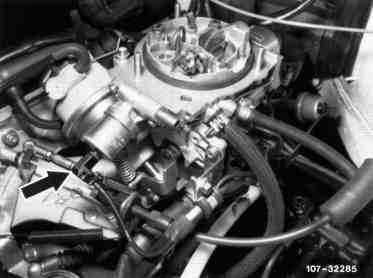
20 Check float chamber vent valve. This is done by detaching connector (arrow) with ignition switched on, and re-fitting again. It must be possible to hear and feel the switching noise of the valve.
Detach hose for float chamber vent at charcoal canister and suck at hose.
Ignition: On. There must not be any continuity.
Ignition: Off. There must be continuity.
If a variation from specification exists,
additionally perform remedy according to
test step 13 (07.2-114, Section "I").
21 Check intake system for leaks by spraying with ISO-Octane DIN 51 756 or cleaning naphtha.
Do not use commercial-grade fuel for spraying (harmful vapors). Pay attention to risk of fire and do not spray on hot parts or parts of the ignition system.
A leak in the inlet manifold exists if:
a) KAT cars: the pointer of the lambda control tester moves to the left.
b) RÜF cars: the idle exhaust emissions level rises.
22 Test idle speed.
If a variation from specification exists, additionally perform test steps according to troubleshooting table 07.2-114, Section G.
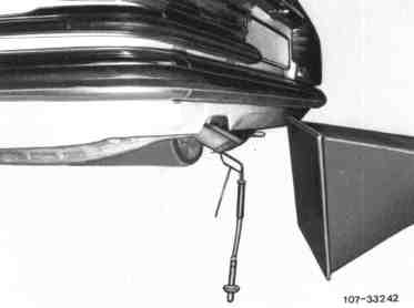
23 Test idle exhaust emissions level of RÜF cars and lambda control of KAT cars, adjust.
RÜF cars
Test idle exhaust emissions level at tail pipe.

KAT cars
Test lambda control.
Move selector lever switch on lambda control tester to 100 % .
Take reading in idle control range. Pointer should swing equally to both sides around the 50 % setting.

Adjust idle exhaust emissions level or lambda control, respectively.
This is done by removing the security plug with puller (028) and adjusting idle exhaust emissions level or lambda control, respectively, by turning the mixture adjusting screw (arrow).
Screwing in = leaner = Lambda reading rises.
Unscrewing = richer = Lambda reading drops.
If on/off ratio reading is constant, it is essential to refer to table "Fault readout with on/off ratio, possible causes of faults, remedy according to test table" (07.2-114, Section "F").
After performing adjustment, press in new security plug (blue) with fitting mandrel (029). Fit on air filter.
Move selector lever into drive position, switch on air conditioning or automatic climate control. Turn power steering to full lock. Engine must run smoothly.
24 Test intake air pre-heater.
a) Intake air temperature below approx.
+20 °C
Determine by visual inspection in connection fitting (12) whether the air flap (9) has fully shut off the "cold air supply" (arrow A).
b) Intake air temperature above approx. +30 °C
Determine by visual inspection in the connection fitting (12) whether the air flap (9) is fully opened to allow the "cold air supply" (arrow A) to pass.
(If variation from specification or function fault exists, replace thermocouple (5)).

Air flap in "warm air" position
11 | Intake manifold |
12 | Connection fitting for warm air hose |
13 | Compensation opening with air guide pipe |
A | Cold air supply |
B | Warm air supply |
5 | Thermocouple |
6 | Control rod |
7 | Compression spring |
8 | Compression spring |
9 | Air flap |
10 | Air filter |

Air flap in "cold air" position
11 | Intake manifold |
12 | Connection fitting for warm air hose |
13 | Compensation opening with air guide pipe |
A | Cold air supply |
B | Warm air supply |
5 | Thermocouple |
6 | Control rod |
7 | Compression spring |
8 | Compression spring |
9 | Air flap |
10 | Air filter |