15-540 Testing electronic ignition system with variable ignition characteristics (EZL)
Operation no. of operation texts and work units or standard texts and flat rates |
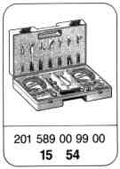
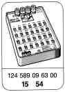
Special tools
Commercially available testers
Multimeter | e.g. Sun, DMM-5 |
Engine tester | e.g. Hermann, Datascope 980 |
Requirements for performing tests on ignition system as described below:
Spark plugs, ignition equipment, distributor rotor and distributor cap in proper mechanical and electrical order.
Test, e.g. by visual inspection, measuring resistance and with ignition oscilloscope.
Note
It is important to pay attention to the safety instructions when performing work on the ignition system (15-505). The ignition must be switched off when unplugging and plugging in the connectors on the electronic ignition control unit.
The test is divided into two sections:
A. Engine not running
In this case, the basic functions of the ignition system are checked.
B. Engine running
Sources of faults in ignition advance or in the appropriate components may affect the car performance.
If complaints are received regarding per-formance, first test the ignition system. Then continue troubleshooting by testing the carburetor system.

S5/3 | High-voltage distributor |
T1 | Ignition coil |
X11 | Diagnostic socket/terminal block terminal TD |
1 | Segment on flywheel/driven plate |
2 | Vacuum line |
030 | Engine tester with oscilloscope |
B11/2 | Coolant temperature sensor (EZL/CIS-E/2 E-E) |
G1 | Battery |
L5 | Crankshaft position sensor |
N1/2 | Electronic ignition control unit |
N45 | 2 E-E carburetor control unit |
R4 | Spark plugs |
R16 | Resistance trimming plug (EZL) |
Test data
Resistances (test data from 0 - 100 °C)
Ignition coil primary (terminals 1 and 15) | W | 0.3 - 0.6 |
Ignition coil secondary (terminals 1 and 4) | kW | 8 - 13 |
Position sensor coil resistance (terminals 7 and 31d) | W | 680 - 1200 |
Insulation of sensor coil (terminal 7 and ground) | kW | 200 |
Distributor cap per connection, distributor rotor, spark plug connector | W | 700 - 1300 |
Voltages, engine not running, ignition switched on
Terminals 15 and 31 (contacts 5 and 2 of diagnostic socket) | V | Battery voltage |
Between terminals 15 and 1 (contacts 5 and 4 of diagnostic socket) | V | 0 |
4-pin circular connector Terminals 15 and 31 | V | Battery voltage |
4-pin circular connector Terminals 16 and 31 | V | Battery voltage |
Dwell angle
at starter speed | 9 - 49° or 10 - 54% |
at 3200 rpm | 27 - 54° or 30 - 60% |
Firing point
at starter speed | TDC 2 °CA |
Engine | Ignition control unit EZL part no. | Engine speed in rpm | Firing point in °CA before TDC | ||
Resistance trim- ming plug setting | without vacuum | with vacuum | |||
102.922 | 004 545 79 32 | 3200 | S | 22 - 26 | 38 - 42 |
102.924 | 004 545 81 32 ww | 3200 | N | 15 - 19 | 38 - 42 |
KAT/RÜF | 006 545 40 32 006 545 41 32 ww | Idle speed | S and N | 11 - 15 | 11 - 15 |
102.922 1) | 006 545 52 32 | 3200 | S | 19 - 23 | 38 - 42 |
102.924 1) | 006 545 53 32 ww | 3200 | N | 14 - 18 | 38 - 42 |
KAT/RÜF | Idle speed | S and N | 11 - 15 | 11 - 15 | |
1) up to 09/88.
2) from 09/88.
ww optionally.
A. Engine not running
Note
If the result obtained from a test step, e. g.
step 1, conforms to the specification, proceed immediately with step 2.
If the result obtained for step 1 is not in conformity with the specification, continue with step 1.1 or 2.
Test step/ Test scope | Tester/ Test connection | Operation/ Requirement | Specification | Possible cause/Remedy |
1. Power supply | N1/1 N1/2 31 15 | Ignition: ON | Battery voltage | Test wiring and contacts according to wiring diagram (from battery via ignition lock to EZL control unit). |
2. Crankshaft position sensor L5 | L5 L5 31d 7 | Detach connector of crankshaft position sensor at EZL control unit. Engine: START | Refer to voltage signal, position sensor Us 1 V | Signal too small or no signal replace crankshaft position sensor. If voltage levels vary test segment. If signal in order replace EZL control unit. |
2.1 | L5 L5 31d 7 | Detach connector of crankshaft position sensor at EZL control unit Ignition: OFF | 680-1200 W | Replace crankshaft position sensor. |
3. Insulation of sensor coil | L5 7 | Detach connector of crankshaft position sensor at EZL control unit. | 200 kW | Replace crankshaft position sensor. |
4. Dwell angle | Engine tester | Engine: START | 1-30° or | Dwell angle not to tolerance replace EZL control unit. If no dwell angle exists test closed circuit cutoff. |
Testing step/ Test scope | Tester/ Test connection | Operation/ Requirement | Specification | Possible cause/Remedy |
4.1 Closed circuit cutoff | T1 T1 Term. 1 Term. 15 | Ignition: ON | 0 V | Replace EZL control unit and ignition coil. |
4.2 | T1 T1 Term. 1 Term. 15 | Engine: START | 0 V | Test wiring and contacts from EZL control unit to ignition coil or replace EZL control unit. |
> 0 V | Replace ignition coil. | |||
4.3 Primary ignition coil T1 | T1 T1 Term. 1 Term. 15 | Ignition: OFF Cables at ignition coil disconnected. | 0.3-0.6 W | Replace ignition coil. |
5. Primary voltage | Oscilloscope image Primary parade | Engine: START | 190-290 V | Replace EZL control unit. |
6. Primary current limiting | Oscilloscope image Overlap Secondary parade | Engine: START | Refer to image of primary current limiting | Replace EZL control unit. |
7. Ignition voltage at terminal 4 of ignition coil | Oscilloscope image Secondary parade | Engine: START | > 8 kV | Test ignition cable terminal 4, distributor rotor, distributor cap, ignition coil. |
7.1 Ignition cable terminal 4 | T1 S5/3 Term. 4 Term. 4 | Ignition: OFF Detach ignition cable terminal 4 at ignition coil and distribu-tional cap. | < 1 W | Replace ignition cable terminal 4. |
7.2 Distributor rotor | Distributor rotor Average Peak | Ignition: OFF Remove distributor cap. | 700-1300 W and visual inspection | Replace distributor rotor. |
7.3 Distributor cap | S5/3 S5/3 Term. 4 Carbon | Ignition: OFF Remove distributor cap and detach ignition cable terminal 4. | 700-1300 W and visual inspection | Replace distributor cap. |
Test step/ Test scope | Tester/ Test connection | Operation/ Requirement | Specification | Possible cause/Remedy |
7.4 Secondary ignition coil T1 | T1 T1 Term. 4 Term. 1 | Ignition: OFF Detach cables at ignition coil. | 8-13 kW | Replace ignition coil. |
8. Ignition voltage at individual cylinder. | Oscilloscope image Secondary parade, connect high-voltage sensor clamp to one cylinder (e.g. cylinder 3). | Engine: START | > 6 kV | Test distributor cap, distributor rotor, ignition cable with spark plug connector, spark plugs. |
8.1 Distributor cap | S5/3 S5/3 | Ignition: OFF Remove distributor cap; measure each individual connection. | 700-1300 W per connection | Replace distributor cap. |
8.2 Distributor rotor | Distributor rotor Average Peak | Ignition: OFF Remove distributor cap. | 700-1300 W | Replace distributor rotor. |
8.3 Ignition cable with spark plug connector | Ignition Spark cable plug connec- tor | Ignition: OFF Detach ignition cable with spark plug connector at distributor and at spark plug. | 700-1300 W | Replace ignition cable with spark plug connector. |
8.4 Spark plug | Visual inspection | Ignition: OFF Remove spark plug. | Electrode gap 0.8 mm | Replace according to findings. |
9. Spark plug | Visual inspection | Ignition: OFF Remove all spark plugs. | Electrode gap 0.8 mm | Replace according to findings. |
B. Engine running
Test step/ Test scope | Tester/ Test connection | Operation/ Requirement | Specification | Possible cause/Remedy |
1. Firing point | Engine tester | Engine: at normal operating temperature; test at specified engine speed. | Refer to table of testing firing point. | EZL resistance trimming plug, idle speed signal, fault situation operation, coolant temperature sensor, vacuum advance, segment. |
1.1 EZL resistance trimming plug (R16) | W10 N1/2 Sensor connec- tor 3 | Ignition: OFF Sensor connector at EZL control unit disconnect. Pay attention to assignment of engine version/resistan- | Depending on resistance trimming plug setting refer to table of resistances for resistance trimming plug. | EZL resistance trimming plug, cables, contacts. |
1.1.1 EZL resistance trimming plug (R16) | R16 R16 Average A-G | Ignition: OFF EZL resistance trimming plug disconnected | Refer to table of resistances for resistance trimming plug. | EZL resistance trimming plug. |
1.1.2 Cables and contacts | R16 N1/2 Sensor connec- tor 3 | Ignition: OFF Sensor connector at EZL control unit and resistance trimming plug disconnected. | < 1 W | Replace cables or contacts. |
W10 R16 | Ignition: OFF EZL resistance trimming plug disconnected | < 1 W | Replace negative cables from EZL resistance trimming plug to engine ground (W10) or contacts. | |
1.2 Coolant temperature sensor (B11/2) | W11 N1/2 Sensor connec- tor 1 | Ignition: OFF Sensor connector at EZL control unit disconnected. | Refer to table for coolant temperature sensor. | Replace coolant temperature sensor, cables or contacts. |
Test step/ Test scope | Tester/ Test connection | Operation/ Requirement | Specification | Possible cause/Remedy |
1.2.1 Coolant temperature sensor (B11/2) | W11 B11/2 | Ignition: OFF Connector at coolant temperature sensor disconnected | Refer to coolant temperature sensor diagram | Replace coolant temperature sensor. |
1.2.2 Cables and contacts | B11/2 N1/2 Sensor connec- tor 1 | Ignition: OFF Connector at coolant temperature sensor and sensor connector at EZL control unit disconnected. | < 1 W | Replace cable or contacts. |
1.3 Idle speed signal | W11 N1/2 Sensor connec- tor 2 | Ignition: ON Sensor connector at EZL control unit disconnected. | Idle speed 0 V battery voltage | |
1.3.1 Cables and contacts | N1/2 N45 2 6 | Ignition: OFF Sensor connector at EZL control unit and connector at electronic carburetor control unit disconnected. | < 1 W | Replace cable or contacts. |
1.4 Vacuum advance | Engine tester | Engine: At normal operat- ing tempera- ture Engine speed: 1500 rpm Detach vacuum hose at EZl control unit. | Firing point is "retarded". | Leak in vacuum hose. Connection at intake manifold clogged. |
Re-fit vacuum hose to EZL control unit. | Firing point is "advanced". | |||
Test step/ Test scope | Tester/ Test connection | Operation/ Requirement | Specification | Possible cause/Remedy |
1.5 1) Fault situation operation | N1/2 G1 4 + | Engine: At normal operat- ing tempera- ture Sensor connector at EZL control unit disconnected. | Battery voltage | Fault at 2 E-E carburetor or cable interrupt between 2 E-E carburetor control unit contact 15 and EZL control unit contact 4. |
1.5.1 1) Cable and contacts | N1/2 N45 4 15 | Ignition: OFF Sensor connector at EZL control unit and connector at electronic carburetor control unit disconnected. | < 1 W | Replace cable or contacts. |
1.6 Segments | Visual inspection | - | Replace flywheel with segment. | |
2. Dwell angle | Engine tester | Engine: At normal operat-ing tempera-ture Disconnect sensor connec- tor and vacuum line at EZL control unit. Engine speed: 3200 rpm. | 27-54° 30-60% | Replace EZL control unit. |
3. High-voltage distributor/ distributor rotor | Visual inspection | Ignition: OFF Distributor cap removed. | - | Distributor cap, distributor rotor has cracks, interference suppression resistors faulty. |
3.1 Distributor cap | S5/3 S5/3 | Ignition: OFF Distributor cap removed. | 700-1300W per connec- tion | Replace distributor cap. |
3.2 Distributor rotor | Distributor rotor Average Peak | Ignition: OFF Distributor cap removed. | 700-1300 W | Replace distributor cap. |
1) Only on cars from 09/88 with ignition control unit 006 545 52 32 or 006 545 53 32.
Test step/ Test scope | Tester/ Test connection | Operation/ Requirement | Specification | Possible cause/Remedy |
4. "Positive" power supply | G1 T1 Term. 15 | Engine: At normal operat- ing tempera- ture Engine speed: idle speed, remove cover on ignition coil. | Voltage may be max. 1 V less than battery voltage. | Transition resistances in cable from battery "positive" to ignition coil terminal 15. |
5. "Negative" power supply | N1/2 G1 31 + | Ignition: OFF Power supply connector on EZL control unit disconnected. | Voltage may be max. 1 V less than battery voltage. | Transition resistances in cable from battery "negative" to EZL control unit contact 31. |
6. Oscilloscope images | | Engine: At normal operat- ing tempera- ture | Refer to oscilloscope images 15-525 | |

Wiring diagram EZL Model 124 prior to 09/88
W3 | Ground, wheelhouse, front left (ignition coil) |
W10 | Ground, battery |
X11 | Diagnostic socket/terminal block, terminal TD |
a | Via plug connection X26 contact 3 to fuse 9 terminal 30 |
b | Via plug connection X26 contact 1 to fuse 7 terminal 15 |
c | No function/cable ends in harness |
B11/2 | Coolant temperature sensor (EZL/CIS-E/2 E-E) |
L5 | Crankshaft position sensor |
N1/2 | EZL control unit |
N45 | 2 E-E carburetor control unit |
R16 | Resistance trimming plug (EZL) |
S5/3 | High-voltage distributor |
T1 | Ignition coil |
Wiring diagram EZL Model 201 prior to 09/88
W3 | Ground, wheelhouse, front left (ignition coil) |
W10 | Ground, battery |
X11 | Diagnostic socket/terminal block, terminal TD |
a | To electrical centre connector S contact 11 |
b | To electrical centre connector S contact 4 |
c | No function/cable ends in harness |
B11/2 | Coolant temperature sensor (EZL/CIS-E/2 E-E) |
L5 | Crankshaft position sensor |
N1/2 | EZL control unit |
N45 | 2 E-E carburetor control unit |
R16 | Resistance trimming plug (EZL) |
S5/3 | High-voltage distributor |
T1 | Ignition coil |

Wiring diagram EZL Model 124 starting 09/88
W3 | Ground, wheelhouse, front left (ignition coil) |
W10 | Ground, battery |
X11 | Diagnostic socket/terminal block, terminal TD |
Z | Terminal sleeve (soldered connector in harness) |
a | Via plug connection X26 contact 3 to fuse 9 terminal 30 |
b | Via plug connection X26 contact 1 to fuse 7 terminal 15 |
B11/2 | Coolant temperature sensor (EZL/CIS-E/2 E-E) |
L5 | Crankshaft position sensor |
N1/2 | EZL control unit |
N45 | 2 E-E carburetor control unit |
R16 | Resistance trimming plug (EZL) |
S5/3 | High-voltage distributor |
T1 | Ignition coil |

Wiring diagram EZL Model 201 starting 09/88
W3 | Ground, wheelhouse, front left (ignition coil) |
W10 | Ground, battery |
X11 | Diagnostic socket/terminal block, terminal TD |
Z | Terminal sleeve (soldered connector in harness) |
a | To electrical centre connector S contact 4 |
b | To electrical centre connector S contact 11 |
B11/2 | Coolant temperature sensor (EZL/CIS-E/2 E-E) |
L5 | Crankshaft position sensor |
N1/2 | EZL control unit |
N45 | 2 E-E carburetor control unit |
R16 | Resistance trimming plug (EZL) |
S5/3 | High-voltage distributor |
T1 | Ignition coil |

Primary current limiting

Diagram of coolant temperature sensor (B11/2)

Voltage signal of position sensor
t1 1st segment
t2 2nd segment
d Period for one crankshaft revolution
Position | Resistance | EZL resistance trimming plug | |
"EZL-ECE" | "EZL-KAT" | ||
| |||
A | W | S | 1 |
B | 2.4 kW | 2 | 2 |
C | 1.3 kW | N | 3 |
D | 750 W | 4 | S |
E | 470 W | 5 | 5 |
F | 220 W | 6 | N |
G | 0 W | 7 | 7 |
Resistances of resistance trimming plugs