15-510 Function of electronic ignition system with variable ignition characteristic (EZL)
Operation no. of operation texts and work units or standard texts and flat rates |

Function diagram of electronic ignition system (EZL) engine 102.922/924 up to 09/88
S5/3 | High voltage distributor |
T1 | Ignition coil |
X11 | Diagnostic socket/terminal block, terminal TD |
1 | Segment at flywheel/driven plate |
2 | Vacuum line |
B11/2 | Coolant temperature sensor (EZL/CIS-E/2 E-E) |
L5 | Crankshaft position sensor |
N1/2 | Electronic ignition control unit |
N45 | 2 E-E carburetor control unit |
R16 | Reference trimming plug (EZL) |

Function diagram of electronic ignition system (EZL) engine 102.922/924 as from 09/88
S5/3 | High voltage distributor |
T1 | Ignition coil |
X11 | Diagnostic socket/terminal block, terminal TD |
1 | Segment at flywheel/driven plate |
2 | Vacuum line |
B11/2 | Coolant temperature sensor (EZL/CIS-E/2 E-E) |
L5 | Crankshaft position sensor |
N1/2 | Electronic ignition control unit |
N45 | 2 E-E carburetor control unit |
R16 | Resistance trimming plug (EZL) |

Arrangement of components
R16 | Resistance trimming plug (EZL) |
S5/3 | High voltage distributor |
T1 | Ignition coil |
B11/2 | Coolant temperature sensor (EZL/CIS-E/2 E-E) |
L5 | Crankshaft position sensor |
N1/2 | Electronic ignition control unit |
N45 | 2 E-E carburetor control unit |
Installation survey
Engine | Model | Version | Output | Compression | EZL resistance trimming plug |
102.922 | 124.020 124.080 | RÜF | 80 kW | 9.1 | EZL-ECE |
102.922 | 124.020 124.080 | KAT | 77 kW | 9.1 | EZL-KAT |
102.924 | 201.023 | RÜF | 77 kW | 9.1 | EZL-ECE |
102.924 | 201.023 | KAT | 75 kW | 9.1 | EZL-KAT |
Components and function
Electronic ignition control unit (N1/2)
1) On cars as of 09/88.
TD signal
Intake manifold vacuum (load state)
Coolant temperature sensor (B11/2)
2 E-E carburetor control unit
EZL resistance trimming plug (R16)
Engine speed and crankshaft position
Coolant temperature
Idle speed or deceleration detection
Fault circuit detection 1) (retarded)
Firing point Adaptation
Pressure sensor
Ignition coil terminal 1
Power
output
stage with
primary
current
limiter
Position sensor (L5)
Ground
Positive
Micro-
computer
The electronic ignition control unit is fitted to the left wheelhouse panel.
It is installed with heat conducting paste to enhance heat dissipation. When replacing, the protective sheeting must not be removed as the sheeting does not impair heat dissipation. The electronic ignition control unit contains a microcomputer, a pressure sensor and the power output stage.

1 Vacuum connection
2 Coaxial connector for control cable from position sensor
3 4-pin sensor connector
1 Temperature sensor
2 Electronic carburetor control unit, connector 6
3 Electronic ignition resistance trimming plug
4 Not allocated (cable terminates in harness) or
electronic carburettor control unit, connector 15 as
from 09/88
4 4-pin power supply connector
15 Terminal 15
16 Ignition coil, terminal 1
TD TD signal
31 Ground
Maps for typical load/engine speed ranges and a fixed idle speed ignition map are stored in the microcomputer of the electronic ignition control unit.
The electronic ignition control unit detects the current operating state of the engine from the various input signals. Engine speed and crankshaft position are detected by the position sensor.
By analyzing all the input signals, the control unit determines the optimum firing point for this operating state from the stored ignition maps.
The power output stage activated by the
microcomputer switches the primary current of
the ignition coil between terminals 16 and 31
(4-pin connector supply).
The electronic ignition control unit also contains the known functions of dwell angle control, no-load current cutoff and primary current limitation.
The engine speed-dependant TD signal is generated in the electronic ignition control unit.
When the engine is started and up to a speed of approx. 250 rpm, the firing point is controlled only by the segment edges of the flywheel.A transition is made from the fixed firing point to the calculated firing point in line with the current operating state only once a certain engine speed is reached (approx. 460 rpm).
The firing point idling is controlled in line with the cooling temperature up to a current temperature of approx. 60 °C to improve warming-up.
Idle speed is detected via a voltage signal from the 2 E-E carburetor control unit (connector 6) to the electronic ignition control unit (connector sensor contact 2).
A transition is made to a fixed map at a cooling temperature in excess of 60 °C.
Note
If there is an interruption to the cooling
temperature sensor (resistance W) a departure
is made from the fixed idle speed map in the
case of Bosch electronic ignition control units
with the part nos. 000 545 79 32, 006 545 40 32
and 006 545 52 32 and a certain firing point in the map selected, i.e. the firing point is "advanced".
At full load, the firing point is determined by the full load ignition map. In this case, the firing point is "advanced" (higher engine torque), allowing for the knock limit.
The electronic ignition control unit detects full load from the intake manifold vacuum and engine speed input signals.
Boiling protection correction
If a certain coolant temperature is exceeded, various ignition maps are "retarded" to counteract any further rise in temperature (refer to table).
Control unit EZL part no. | Temperature range | Firing point retarded by |
004 545 79 32 004 545 81 32 | 100 - 105 °C | 4 °CA |
006 545 40 32 006 545 41 32 | 90 - 100 °C | 6 °CA |
006 545 52 32 006 545 53 32 | 90 - 100 °C | 6 °CA |
The firing point of certain ignition maps may be adjusted with the EZL resistance trimming plugs according to the operating state.
On cars from 09/88 the electronic ignition control unit (connector sensor contact 4) receives a ground signal from the 2 E-E carburetor control unit (contact 15).
The following fault section results in a fault situation being activated:
- 20% on/off ratio readout
- Interrupt in cable between electronic ignition control unit (connector sensor contact 4) and 2 E-E carburetor control unit (contact 15).
If this fault is detected, the ground signals are interrupted and the firing point is "retarded" to 12 °CA after TDC as a function of coolant temperature, engine speed and throttle valve angle (refer to Testing throttle valve actuator fault signal for electronic ignition control unit combustion I, 07.2-114, test step 14).

Crankshaft position sensor (L5)
To control the electronic ignition control unit, the position sensor detects the crankshaft position and engine speed.
The position sensor is installed above the starter motor flange (arrow) on the crankcase.
The coil body projects to shortly before the segments on the flywheel or driven plate. The segment position and engine speed are detected contactlessly.

The rotating engine produces an alternating
voltage in the position sensor as a result of
induction. The peak voltage level (Us) is approx.
1.5 Volts at starter's speed. As engine speed
increases, the voltage rises (Us approx. 3 Volts
at 1200 rpm).
Note
Measure peak voltage level (Us) with the oscilloscope.
The crankshaft position is detected from the voltage as follows:
The segment front edge generates a negative voltage signal.
The segment rear edge generates a positive voltage signal.
Engine speed is determined by measuring the period.

Position sensor voltage signal
t1 1st segment
t2 2nd segment
d Period for crankshaft revolution
The alternating voltage from the position sensor is passed via the control cable (coaxial cable) to terminal 7 of the electronic ignition control unit. This is a single-wire cable, with the screening being used as a second cable.
If the electronic ignition control unit does not receive a signal from the position sensor, the complete ignition system is non-operative, e.g. the cause may be an interrupt in the sensor coil.
The resistance of the position sensor is
680 - 1200 W.

Segments
There are two segments offset by 180° (arrows) fitted to the flywheel and to driven plate, respectively.
A Driven plate with ring gear (automatic
transmission)
B Flywheel (manual transmission)
Instructions regarding damaged segments or mechanical damage to position sensor:
Alternating voltage of position sensor less than specification.
Alternating signals of individual segments differ considerably.
No alternating voltage signal.
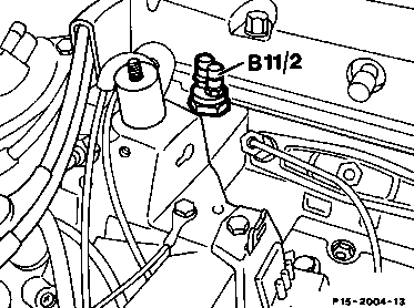
Coolant temperature sensor (B11/2)
The coolant temperature sensor has two NTCs each with a single-pin connection. One NTC for 2 E-E CIS-E and one NTC for the electronic ignition system (EZL).
The temperature signal passes along the green/black cable and through the 4-pin connector sensor (contact 1) to the electronic ignition control unit. The temperature sensor is located at the front left of the cylinder head.
Note
NTC=Negative temperature coefficient thermistor, i. e. the resistance is less in the warm state.

As of September 1989 the electronic ignition system EZL is provided with a 4-pin coolant temperature sensor. This sensor integrates two independent temperature sensors (NTC) which do not have any electrical connection to the housing of the coolant temperature sensor.

One temperature sensor is for the EZL electronic ignition system (contacts 1 and 3) and one for the 2 E-E carburetor (contacts 2 and 4).
The connector of the coolant temperature sensor is designed in such a way that it can be plugged in in any position. The arrangement of the two temperature sensors is diagonal.

Pin assignment of coupling:
1=EZL temperature sensor
2=2 E-E carburetor temperature sensor
3=Engine ground at intake manifold for EZL
4=Control unit ground of 2 E-E carburetor
Notes regarding testing coolant temperature sensor (B11/2)
When testing the coolant temperature sensor, the resistances should be measured and compared 2 diagonally. The resistances of the characteristic curves are identical with those of the previous version.
A. Electronic ignition resistance trimming plug (R16)

It is possible to adjust the firing points of certain ignition maps according to the operating mode with the electronic ignition resistance trimming plug. This enables the firing point to be adapted to the available fuel (premium "S" and regular "N").
It is also possible for the customer to perform this adjustment to premium or regular grade fuel (refer to Owner's manual).
Note
Operating the car with premium grade fuel produces optimum engine performance and consumption levels.
The resistance network of all the electronic ignition resistance trimming plugs is identical. The electronic resistance trimming plugs differ only in their inscription.
The inscription is a means for assigning the respective plug positions to the following resistances:
Position | Resistance | Electronic ignition resistance trimming plug | |
"EZL-ECE" | "EZL-KAT" | ||
| |||
| |||
A | W | S | 1 |
B | 2.4 kW | 2 | 2 |
C | 1.3 kW | N | 3 |
D | 750 W | 4 | S |
E | 470 W | 5 | 5 |
F | 220 W | 6 | N |
G | 0 W | 7 | 7 |
|

There are no resistors in the bottom section of the plug. The respective resistance of the electronic ignition resistance trimming plug is tapped between the centre jack and the contacted outer contact.

The various resistors are positioned in the electronic ignition resistance trimming plug between the outer and inner connector pins.
The electronic ignition control unit detects the connected resistance between the electronic ignition resistance trimming plug and ground.
Perform resistance measurements for testing
he electronic ignition resistance trimming plug on the EZL control unit between connector sensor (3) and ground.
Note
There is no connector pin provided in position A.

High-voltage distributor (S5/3)
The sole task of the high-voltage distributor is to distribute the ignition voltage. It is not therefore possible to alter the setting of the firing point.
The high-voltage distributor is installed in the identical position with that of the ignition distributor.
The firing point is determined by the electronic ignition control unit.
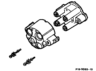
The distributor cap is attached to the distributor with M6 special screws. The protective cap for long-distance interference suppression is mounted on the distributor cap and fixed in place with two star-shaped metal plates.
Interference suppression resistances: spark plug connector, distributor rotor and distributor cap per connection 700-1300 W.

Ignition coil (T1)
The ignition coil is matched to the electronic ignition control unit to achieve a higher ignition energy. As a result of the high make-break capacity of the electronic ignition control unit, it is possible to further increase the primary current. The primary winding is designed to have a very low impedance (0.3 - 0.6 W) for this purpose.
No-load current cutoff and primary current limitation enable the ignition coil to operated without a series resistor, which eliminates current limitation as a result of the series resistor. If the maximum primary current flows unlimited in the ignition coil (e.g. as a result of no-load current cutoff fall), the ignition coil would be damaged after a short time by the excess of heat which would develop.
Distinguishing feature:
The ignition coils on 4- and 6-cylinder engines with electronic ignition systems are identical.
Identification: yellow type plate.
The ignition coils cannot be interchanged with the ignition coils for 8-cylinder engines (identification: green type plate). Pay attention to the part no. when installing a new ignition coil.
Pay attention to instructions for performing work on electronic ignition systems (15-505).