07.2-090 Description of Design and Function
A. General
Carburetor designation 2 E-E
2=Two stages
E=Series
E=Electronically controlled
B. Brief description
The 2 E-E carburetor is a downdraft two-stage carburetor of known design, but which has been significantly simplified in its basic configuration. The traditional control devices for start, warming-up and acceleration enrichment, as well as the idle shutoff valves have been eliminated.
The functions of the eliminated control devices are performed by two actuators, the choke actuator (Y22/1) and the throttle valve actuator (Y22/2), which are controlled by an electronic microprocessor control unit (mapped control).

2 E-E carburetor
3 | 2nd stage aneroid cell |
6 | Choke |
8 | Carburetor cover |
9 | Carburetor body |
28 | Needle control, idle air nozzle |
R24 | Throttle valve potentiometer |
Y18 | Float chamber vent valve |
Y22/1 | Choke actuator |
Y22/2 | Throttle valve actuator |
In the basic harmonization of the nozzle system, the carburetor is adapted to the needs of the engine running at normal operating temperature at the lean end. The remaining composition of the mixture is achieved by enrichment.
Good emergency running properties are assured in the event of the electronic mixture control failing.
The choke actuator is an electric motor with a very high adjusting speed. It closes or opens the choke and thus adapts the mixture to the actual operating conditions.
When the engine is idling or in the near-idling range, the mixture is influenced by an idling air correction needle, which is also operated by the choke actuator. In addition, the choke actuator also operates the fuel cutoff if the maximum permissible engine speed is exceeded.
The throttle valve actuator is an electropneumatic actuator which controls engine speed when idling, during cold start and warming-up. The throttle valve actuator also controls decel fuel cutoff and engine stop.
In the catalytic converter mode with oxygen sensor, a closed control loop (oxygen sensor, control unit, choke and needle control of idling air nozzle) ensures that the composition of the mixture is maintained precisely at around lambda=1.
To avoid the carburetor being flooded by a downflow of gasoline, the fuel pump is designed to be through-flow protected and a check valve is installed in the fuel return hose at the carburetor.

Function diagram 2 E-E carburetor with lambda control
17 | Catalytic converter |
a | Intake manifold heater relay control (K3) |
b | Idle signal for EZL control unit (N1/2) |
c | Lambda test signal (diagnosis X11) |
f | Engine speed signal (TD) |
g | A/C compressor cut-in signal |
h | Drive position cut-in signal (automatic transmission) |
i | Resistance trimming plug signal (KAT or RÜF) |
k | Coolant temperature signal for control unit (N1/2) |
B11/2 | Coolant temperature sensor (EZL/CIS-E/2 E-E) |
G3/2 | Heated oxygen sensor |
N45 | 2 E-E carburetor control unit |
R8 | Intake manifold heater |
R24 | Throttle valve potentiometer |
Y22/1 | Choke actuator |
Y22/2 | Throttle valve actuator |
6 | Choke |
8 | Carburetor |
11 | Air filter |
14 | Intake manifold |

Catalytic converter or retrofit cars are equipped
with a fuel evaporation control system. The fuel
vapours from the fuel tank and from the float chamber are stored in a charcoal canister and supplied in a metered flow to the engine (refer to Function of float chamber vent, section H).
Function diagram fuel evaporation control system
1 Carburetor
36a 50 °C thermovalve, red
52 Charcoal canister (fuel tank)
52/1 Charcoal canister (float chamber), phased
implementation
53 Regeneration valve
A Extraction port
B To fuel tank
C Vacuum port
D Phased implementation
C. Components, arrangement of components

R8 | Intake manifold heater |
R8/1 | 2 E-E carburetor heater |
R19 | 2 E-E resistance trimming plug |
R24 | Throttle valve potentiometer |
Y18 | Float chamber vent valve |
Y22/1 | Choke actuator |
Y22/2 | Throttle valve actuator |
B11/2 | Coolant temperature sensor (EZL/CIS-E/2 E-E) |
G3/2 | Heated oxygen sensor |
K1/1 | Overvoltage protection relay 87E, 7-pin |
K3 | Intake manifold heater relay |
N6 | A/C compressor cutoff control unit |
N15 | Kickdown cutoff relay |
N45 | 2 E-E carburetor control unit |

2 E-E carburetor components
R24 | Throttle valve potentiometer |
Y18 | Float chamber vent valve |
Y22/1 | Choke actuator |
Y22/2 | Throttle valve actuator |
3 | 2nd stage aneroid cell |
B11/2 | Coolant temperature sensor (EZL/CIS-E/2 E-E) |
G3/2 | Heated oxygen sensor |
K1/1 | Overvoltage protection relay 87E, 7-pin |
N45 | 2 E-E carburetor control unit |
R19 | 2 E-E resistance trimming plug |
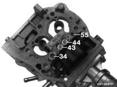
Carburetor cover
It can be removed and contains the following parts:
1st and 2nd stage pre-atomizer.
1st and 2nd stage main nozzle systems
(43, 44).
Idling system with needle-controlled idle air nozzle.
Float system (hollow chamber float).
Float chamber vent valve.
Choke (VD).
Fuel supply and return connections. The supply connection has an integrated strainer.
2nd stage full load enrichment pipe, calibrated.
2nd stage transition system.
Fuel cutoff.
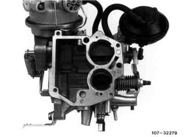
Float body
It contains the two throttle valves of the 1st and 2nd stages, as well as the vacuum connections for the fuel evaporation control system and the automatic transmission.
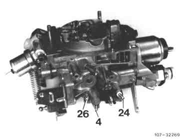
Arrangement of vacuum connections
4 Port for automatic transmission
24 Control port for regeneration valve of fuel evaporation control system (white ring)
26 Extraction port for fuel evaporation control system
(brown ring)

Throttle valve actuator
It performs the following tasks:
Controlling engine speed when engine is started and warming-up.
Controlling idling speed.
Deceleration fuel cutoff.
Engine stop.
Y22/2 Throttle valve actuator
92 Evacuation port
93 Air admission port
The throttle valve actuator is an electropneu- matic actuator with two electromagnetic valves, a diaphragm, a logarithmic potentiometer and a plunger. The potentiometer protects the position of the plunger at that moment and inputs this signal to the electronic control unit. | By admitting or releasing air to or from the diaphragm chamber, the desired engine speed is reached. The two electromagnetic valves are controlled by the electronic control unit. A filter is integrated in the air admission port (atmospheric side) and a check valve in the evacuation port (vacuum side). |

Choke actuator
It performs the following tasks:
Operates the choke and the idle air correction needle.
Limits maximum engine speed by cutting off the fuel supply.
The choke actuator (Y22/1) is a torque motor
with a high adjusting speed (approx.
30 milliseconds for a 90° change in angle).
It operates the choke by means of a rod. The mixture ratio is controlled by means of the choke in all operating ranges, with the exception of idling and the near-idling range.
The choke actuator is controlled with a base frequency of 100 Hz. The choke is moved into the appropriate position by varying the current (on/off ratio).

Needle control of idle air nozzle
This peforms the following task:
Adapting mixture in idling and near-idling range by altering the idle correction air quantity.
6 Choke
29 Lever for operating needle control
30 Idle air nozzle
31 Idle air correction needle
32 Compression spring
33 Mixing tube
34 Idle fuel nozzle
35 Lever for operating fuel cutoff
61 Rod for operating fuel cutoff
The needle control is connected to the choke. In view of the low air throughput in the idling and near-idling range, it is not possible to control the mixture via the main nozzle system. | In these ranges, the mixture is controlled by a correction needle which is more or less immersed in the idle air nozzle and which influences the idle air quantity. |

Throttle valve potentiometer
It performs the task of detecting the following information and inputting it to the electronic control unit:
Position of 1st stage throttle valve from the throttle valve angle (load detection).
Speed of throttle valve angle change during acceleration (slight or sharp acceleration enrichment).
Direction of rotation of throttle valve detecting acceleration or deceleration or decel fuel cutoff.
Idle signal detection for ignition system and electronic idle speed control.
The throttle valve potentiometer (R24) is a rotary potentiometer with an integrated torsion return spring which is connected to the 1st stage throttle valve shaft by a loose-fitting sleeve coupling. |

Electronic control unit
The control unit (45) is a digital configuration employing a microprocessor. There are two mixture maps stored in the control unit, for operation without or with lambda control. The control unit is housed in the front right of the component compartment close to the battery.
N45 2 E-E carburetor control unit
K1/1 Overvoltage protection relay 87E, 7-pin
N6 A/C compressor cutoff control unit
N15 Kickdown cutoff relay
The control unit performs the following functions: Controlling start and warming-up mixture Controlling idle speed Acceleration enrichment Map control Decel fuel cutoff Engine stop Lambda control Heating intake manifold and bypass Limiting maximum engine speed Control of ignition in the event of faults at throttle valve actuator Control unit input signals Coolant temperature. Engine speed (TD signal). Position and sequence of movement of throttle valve via throttle valve potentiometer. Plunger position of throttle valve actuator via potentiometer of throttle valve actuator. |
Gear detection of automatic transmission via starter lockout switch. A/C compressor cut-in signal via A/C compressor control unit. Lambda signal via oxygen sensor. Resistance trimming plug detection (KAT or ECE map plug). Control unit output signals Choke actuator. Throttle valve actuator. Idle signal for control unit of ignition system. Lambda test signal for diagnostic socket. Intake manifold and bypass heater. Fault signal for ignition control unit in the event of faults in throttle valve actuator. |
Overvoltage protection relay (K1/1)
This protects the electronic control unit from overvoltages. The overvoltage protection is housed in the front right of the component compartment close to the battery; a 10 A fuse is located on the top.

Coolant temperature sensor
The temperature sensors (arrow) detect the coolant temperature. One sensor transmits its data to the electronic control unit of the 2 E-E carburetor, the other to the control unit of the ignition system.

Resistance trimming plug for 2 E-E carburetor electronic control unit
For activating the two mixture maps (KAT or ECE map) stored in the control unit, two different resistance trimming plugs are required.
For catalytic converter cars, resistance trimming plug with the inscription "KAT" or for retrofit cars, resistance trimming plug with the inscription "ECE". The resistance trimming plug has a security seal.
Resistance trimming plug for retrofit
cars (RÜF) with inscription "ECE"

Resistance trimming plug for catalytic
converter cars (KAT) with inscription
"KAT"
Basic setting of resistance trimming plugs The basic setting of the resistance trimming plug for the electronic control unit of catalytic converter or retrofit cars is position "1". |
The remaining intermediate positions of the resistance trimming plug up to "7" permit the mixture maps to be individually adapted should customer complaints be received (refer to Test and adjustment work 07.2-114). |
Oxygen sensor Refer to Group 14 for description of design | Description of function |
D. Function diagram 2 E-E carburetor system with lambda control
a | Intake manifold heater relay control (K3) |
b | Idle signal for ignition control unit (N1/2) |
c | Lambda test signal (diagnosis, X11) |
f | Engine speed signal (TD) |
g | A/C compressor cut-in signal |
h | Drive position cut-in signal (automatic transmission) |
i | Resistance trimming plug signal (KAT or RÜF) |
B11/2 | Coolant temperature sensor (EZL/CIS-E/2 E-E) |
G3/2 | Heated O2 sensor |
N45 | 2 E-E carburetor control unit |
R8 | Intake manifold heater |
R24 | Throttle valve potentiometer |
Y22/1 | Choke actuator |
Y22/2 | Throttle valve actuator |
6 | Choke |
8 | Carburetor |
11 | Air filter |
14 | Intake manifold |
17 | Catalytic converter |
E. Block diagram 2 E-E carburetor system
Ignition starter switch (S2/1), terminal (15)
2 E-E carburetor control unit (N45)
Coolant temperature sensor (B11/2)
Throttle valve potentiometer (R24)
Heated oxygen sensor (G3/2)
Starter lockout/reversing light switch (S16/1)
A/C compressor cutoff control unit (N6)
Overvoltage protection relay (K1/1), terminal (30a), terminal 87L (15)
Battery ground (W10)
Engine ground (W11)
Electronic ignition (EZL) control unit
Throttle valve actuator (Y22/2)
Resistance trimming plug (R19) (2 E-E)
Voltage supply
Battery (+) terminal (30) from terminal block (X35)
Ground supply
Coolant temperature signal
TD signal (engine speed)
Throttle valve angle
Plunger position (engine speed control)
KAT or RÜF detection signal
Drive position signal (automatic transmission)
Oxygen sensor signal
Air conditioning cut-in signal
Throttle valve actuator (Y22/2) controls:
Engine speed control (start, warming-up, idling)
Decel fuel cutoff
Engine stop
Choke actuator (Y22/1) controls:
Choke for adapting mixture to particular operating condition
Fuel cutoff for limiting maximum engine speed
Idle speed detection for electronic ignition control unit (N1/2)
Signal for fault circuit if fault exists at throttle valve actuator
Inlet manifold+bypass heater relay control (K3)
Lambda test signal for diagnosis socket (X11)
F. Sectional view of carburetor

44 | 2nd stage main nozzle |
45 | Closing plate for fuel cutoff |
46 | 2nd stage throttle valve |
47 | 2nd stage bypass slot |
48 | 2nd stage pre-atomizer |
49 | 2nd stage full load enrichment pipe |
50 | 2nd stage transition system mixing pipe |
51 | 2nd stage air correction nozzle with mixing pipe |
52 | 1st stage air correction nozzle with mixing pipe |
53 | 1st stage pre-atomizer |
54 | Manipulation lock |
55 | 2nd stage transition fuel nozzle |
73 | 2nd stage transition mixing passage |
74 | 2nd stage transition system fuel supply passage |
75 | 2nd stage transition system air passage |
76 | Retraction passage (2nd stage transition) |
77 | Retraction passage (full load enrichment pipe) |
R8/1 | 2 E-E carburetor heater |
6 | Choke |
8 | Carburetor cover |
9 | Carburetor body |
29 | Needle control mechanism (idle correction air) |
30 | Idle air nozzle |
31 | Idle air correction needle |
32 | Compression spring |
33 | Mixing tube for idle mixture |
34 | Idle fuel nozzle |
38 | Carburetor cover gasket |
39 | Idle mixture adjusting screw |
40 | 1st stage bypass slot |
41 | Idle mixture outlet |
42 | 1st stage throttle valve |
43 | 1st stage main nozzle |
G. Float device/fuel cutoff

Float device/fuel cutoff
59 | Float shaft |
60 | Float stop |
61 | Actuating rod |
62 | Compression spring |
63 | Passage |
64 | Recirculating air adjusting screw (factory-set) |
65 | Manipulation lock |
6 | Choke |
22 | Fuel supply connection |
23 | Fuel return connection |
35 | Lever |
42 | 1st stage throttle valve |
45 | Closing plate |
56 | Float |
57 | Float needle seat |
58 | Float needle |
Float device The float device operates according to the already known principle. The float needle (58) is "automatically opened" by the float, thus avoiding the float needle jamming. The float travel down the way is limited by the stop (60). |
The float level is fixed by the press-fitted depth of the float needle seat, and therefore cannot be varied. |
Fuel cutoff (Limiting engine maximum speed) The electronic control unit is supplied with the engine speed signal through contact 25. If an engine speed of 615050 rpm is exceeded, the current flow direction for the choke actuator is reversed (poles reversed) in the control unit, the choke (6) opens and moves into the vertical position. |
The closing plate (45) is now pulled against the nozzle assy by means of lever (35), actuating rod (61), thus blocking the fuel supply to all the fuel-conveying systems. Once the engine speed has dropped below approx. 6100 rpm, the fuel supply is restored. |
H. Float chamber vent

Float chamber vent
68 | Valve plate |
69 | Compression spring |
Y18 | Float chamber vent valve |
37 | External vent port |
67 | Internal vent passage (to clean air side of air filter) |
When the ignition is switched off, the float chamber vent valve (Y18) is de-energized and switches to "external venting". The fuel vapours are drawn through the external vent port (37) to atmosphere or passed into a charcoal canister where they are stored. When the engine is running, the stored fuel vapours are drawn off and combusted. | When the ignition is switched on, the float chamber vent valve (Y18) is energized, the solenoid picks up, the valve switches to "internal venting". A link is created between float chamber and clean air side of air filter. |
I. Start

Cold start
43 | 1st stage main nozzle |
52 | 1st stage air correction nozzle |
53 | 1st stage pre-atomizer |
70 | Idle mixture passage |
71 | Idle fuel passage |
6 | Choke |
32 | Compression spring |
40 | 1st stage bypass slot |
41 | Idle mixture outlet |
42 | 1st stage throttle valve |
A voltage (via terminal 30a battery+) exists constantly at contact 1 of the control unit, even when the ignition is switched off. The choke (6) is opened fully by the force of the compression spring (32). When the ignition is switched on, the control unit is supplied additionally with voltage via contact 13 (= terminal 15 ignition), it is activated and allows a 100 Hz clocked current to flow to the choke actuator. The choke moves slightly into the closed position. | The plunger of the throttle valve actuator is fully extended and has moved the throttle valve (42) into the start position. |
Start procedure at coolant temperature When the engine is started, the control unit is supplied with the engine speed signal (TD signals) through contact 25 and allows a current, determined by engine temperature and the mixture map stored in the control unit, to flow to the choke actuator. The coolant temperature signal is input to the control unit through contact 21. The current existing at the choke actuator now closes the choke to a certain position (start position). After the engine has started, the control unit detects engine self-running through contact 25 (TD signal), reduces the current, and the choke moves back to the matching warming-up map position. | Start procedure at coolant temperature If the coolant temperature is below+18 °C, the choke actuator is supplied immediately with a relatively high current when the ignition is switched on, the choke (6) is fully closed to ensure that the engine starts immediately even at low temperatures. After the engine has started (engine self-running), the current existing at the choke actuator is reduced and the choke moves back to the matching warming-up map position. |
Repeat start If a repeat start is performed, the choke closes in line with the particular coolant temperature, and the plunger of the throttle valve actuator moves back into start position. | Automatic opening of choke If the starting mixture is over-enriched when starting the engine from cold, the choke can be opened fully electrically by applying full throttle to produce a leaner starting mixture. |
J. Warming-up

Warming-up
43 | 1st stage main nozzle |
52 | 1st stage air correction nozzle |
53 | 1st stage pre-atomizer |
70 | Idle mixture passage |
71 | Idle air passage |
6 | Choke |
30 | Idle air nozzle |
31 | Idle air correction needle |
40 | 1st stage bypass slot |
41 | Idle mixture outlet |
42 | 1st stage throttle valve |
To ensure that the mixture is not too rich when the engine is started at a coolant temperature <+18 °C, the control unit reduces the current supply to the choke actuator after the starting speed is exceeded (=self-running), the choke (6) opens slightly, the mixture is leaned to the warming-up mixture. At the same time, as engine speed increases and exceeds the specified idling speed (at | The throttle valve actuator is now activated by the control unit and pulls the plunger back far enough for the engine to run at an idle speed corresponding to the coolant temperature. |
The warming-up mixture in the idling and near-idling range is influenced by the needle control of the idle correction air dependent on the choke position. | Up to normal engine operating temperature, the warming-up mixture is controlled in line with the warming-up mixture map stored in the control unit as a function of the coolant temperature. At normal engine operating temperature, the choke is not vertical but is moved against the closing position. |
K. Idling, idle correction air needle control

Idling
40 | 1st stage bypass slot |
41 | Idle mixture outlet |
42 | 1st stage throttle valve |
43 | 1st stage main nozzle |
70 | Idle mixture passage |
71 | Idle fuel passage |
72 | Idle reserve |
6 | Choke |
30 | Idle air nozzle |
31 | Idle air correction needle |
32 | Compression spring |
33 | Mixing pipe (idle system) |
34 | Idle fuel nozzle |
39 | Idle mixture adjusting screw |
With the exception of certain differences which are described below, the operating principle of the idle system is identical to that of previous carburetors.
Idle correction air needle control
6 Choke
29 Lever
30 Idle air nozzle
31 Idle air correction needle
32 Compression spring
33 Mixing pipe
34 Idle fuel nozzle
35 Lever for operating fuel cutoff
61 Rod for operating fuel cutoff
Idle correction air needle control
The idle mixture is influenced by varying the cross-section of the idle air nozzle (30) by means of the correction needle (31).
The choke (6) is turned into a certain position in line with the idle map stored in the control unit. This results in the correction needle (31), which is attached to the choke, likewise being moved into a predetermined position.
L. Electronic idle speed control
The idle speed control continuously compares actual idle speed with set idle speed according to a map stored in the control unit. Variations in engine speed of >40 rpm are corrected with the throttle valve actuator (Y22/2). The idle speed detection is formed from the potentiometer signal of the throttle valve actuator and the signal of the throttle valve potentiometer. Idle speed is constantly maintained at a certain level over the entire temperature range dependent on the coolant temperature, selector lever of automatic transmission in drive position or A/C compressor switched on. | The gear engaged in the automatic transmission is detected via contact 16 of the control unit and terminal 50 of the starter lockout switch. A/C compressor on is detected via contact 19 of the control unit. After the engine starts, engine speed is slightly higher for a short time. |

Electronic idle speed control
a | Intake manifold heater relay control (K3) |
b | Idle signal for ignition control unit (N1/2) |
c | Lambda test signal (diagnosis, X11) |
d | Coolant temperature signal |
e | Oxygen sensor signal |
f | Engine speed signal (TD) |
g | A/C compressor cut-in signal |
h | Drive position cut-in signal (automatic transmission) |
i | Resistance trimming plug signal (KAT or RÜF) |
B11/2 | Coolant temperature sensor (EZL/CIS-E/2 E-E) |
G3/2 | Heated oxygen sensor |
N45 | 2 E-E carburetor control unit |
R24 | Throttle valve potentiometer |
Y22/1 | Choke actuator |
Y22/2 | Throttle valve actuator |
6 | Choke |
11 | Air filter |
12 | Carburetor |
If the set idling speed is exceeded, current pulses are supplied to the "evacuation valve" (96) through connector 3 of the throttle valve actuator from contact 9 of the control unit (N45). The valve opens, the engine vacuum acts in the diaphragm chamber, the plunger (101) is pulled back far enough for the set idle speed to be reached. | If engine speed drops below set idle speed, current pulses are supplied to the "air admission valve" (97) through connector 8 of the throttle valve actuator from contact 3 of the control unit (N45). Air is admitted to the diaphragm chamber, the plunger (101) extends far enough for the set idle speed to be reached. |
M. 1st stage main nozzle system and acceleration

Transition to 1st stage main nozzle system and acceleration
41 | Idle mixture outlet |
42 | 1st stage throttle valve |
43 | 1st stage main nozzle |
52 | 1st stage air correction nozzle with mixing pipe |
53 | 1st stage pre-atomizer |
R8/1 | 2 E-E carburetor heater |
6 | Choke |
30 | Idle air nozzle |
31 | Idle air correction needle |
34 | Idle air fuel nozzle |
40 | 1st stage bypass slot |
The acceleration mixture map is stored in the control unit. Enrichment of the mixture when accelerating is performed by closing the choke (6) to a defined position as a function of coolant temperature, engine speed, throttle valve angle and throttle valve opening speed. The last two influencing parameters are detected by the throttle valve potentiometer and input to the control unit via contacts 7, 11, 18. Acceleration enrichment is not activated when the car accelerates slowly. The transition enrichment until the main nozzle comes into play is performed solely via the slot bypass system (40). | When the car accelerates, the control unit supplies more or less current to the choke actuator depending on the intensity of acceleration (speed of change in angle at throttle valve potentiometer). Sharp acceleration = large current, choke closes more Slight acceleration = small current, choke closes less The vacuum in mixing chamber increases and fuel is now supplied via the idle, bypass and main nozzle system. Once acceleration is completed, the choke moves back with a time delay to a position corresponding to the mixture map for constant operation. |
N. Bypass heater

The bypass system is heated by a PTC heating element to prevent the bypass system icing up at outside temperatures around the freezing point in combination with high air humidity.
A voltage is supplied to the heating element when the engine is started. The heater is switched off once the coolant temperature is approx.+60 °C, controlled by the control unit. Electrically, the heating element is connected in parallel to the intake manifold heater.
O. Part load and transition to 2nd stage main nozzle system

Part load and transition to 2nd stage main nozzle system
55 | 2nd stage transition fuel nozzle |
73 | 2nd stage transition mixture passage |
74 | 2nd stage transition system fuel supply passage |
76 | Retraction passage |
6 | Choke |
46 | 2nd stage throttle valve |
47 | 2nd stage bypass slot |
50 | 2nd stage transition system mixing pipe with air admission |
Part load At constant operation in part load range, the mixture is controlled by a mixture map stored in the control unit. The control unit constantly scans the information regarding coolant temperature, engine speed, throttle valve angle or throttle valve stationary. |
These data form the basis for determining a current from the mixture map, which is supplied to the choke actuator. The choke adopts the corresponding position. |
Transition to 2nd stage main nozzle system The throttle valve (46) of the 2nd stage is operated with vacuum through the aneroid cell (3) of the 2nd stage in line with the opening angle of the throttle valve of the 1st stage, as well as the air throughput. |
The design of the lever system ensures that the 2nd stage opens progressively only after the throttle valve of the 1st stage has opened two-thirds. When the 1st stage throttle valve is closed, the 2nd stage is automatically closed mechanically by the lever (81) (forced return). |

Throttle valve mechanism
1st and 2nd stage
3 2nd stage aneroid cell
9 Carburetor body
27 1st stage throttle valve
lever
42 1st stage throttle valve
46 2nd stage throttle valve
78 Stop screw (1st stage
throttle valve basic
setting)
79 Stop for decel fuel
shutoff
80 Torsion spring
81, Plastic element (for
82 lock and 2nd stage
positive return element)
83 Lever for operating
cruise control
84 Idle stop screw
87 2nd stage actuating lever
(with driving fork)
88 Torsion spring
89 Actuating rod
To ensure lag-free transition from the 1st stage to the moment where the main nozzle system of the 2nd stage comes into play, a bypass slot (47) is provided below the 2nd stage throttle valve (46). When the 2nd stage throttle valve opens, the fuel mixture flows through the transition fuel nozzle (55), mixing pipe (50) and passage (73) (refer to Section "O"). | The correction air flows in through the port in the mixing pipe (50). The mixing pipe has a retraction passage (76) to ensure that no fuel can flow on out of the bypass slot if the engine is switched off when hot. |
P. Full load

Full load
48 | 2nd stage pre-atomizer |
49 | 2nd stage full load enrichment pipe |
53 | 1st stage pre-atomizer |
77 | Retraction passage |
6 | Choke |
40 | 1st stage bypass slot |
42 | 1st stage throttle valve |
46 | 2nd stage throttle valve |
47 | 2nd stage bypass slot |
At full load, the choke is moved into an almost vertical position by the choke actuator. Both main nozzle systems are operational from a moderate engine speed. As the air flow increases, fuel is drawn in additionally through the full load enrichment pipe (49) (maximum output).
A retraction passage (77) is provided to avoid fuel dripping out of the full load enrichment pipe if the engine is switched off when hot.
Q. Deceleration and engine stop

Deceleration and engine stop
41 | Idle mixture outlet |
42 | 1st stage throttle valve |
6 | Choke |
40 | 1st stage bypass slot |
Decel fuel cutoff
If the accelerator is fully released, the control unit detects deceleration above a deceleration speed threshold and the throttle valve of the 1st stage (42) is closed by the throttle valve actuator after a time delay far enough for the idle mixture outlet (41) and the bypass slot (40) to be in the atmospheric range. The fuel delivery from the idle and bypass system is interrupted.
Decel fuel cutoff is operational provided the following conditions are met: Engine speed higher than deceleration speed threshold, e. g.: engine at normal operating temperature: > 1400 rpm for manual transmission > 1100 rpm for automatic transmission Decel fuel cutoff (accelerator not depressed). The throttle valve potentiometer (R24) is operated through contact 2 by a voltage of approx. 5 Volts from contact 18 of the control unit. As a result of a change in the resistance at the rotary potentiometer, the control unit detects the position (angle setting) of the throttle valve and, by the change in the direction of rotation at the potentiometer, that the accelerator is being released. | As soon as the accelerator has been fully released, the throttle valve lever (27) is resting against the plunger (101) of the throttle valve actuator (Y22/2). The control unit (N45) now detects idling with deceleration from the two potentiometer signals (throttle valve actuator and throttle valve potentiometer). Decel fuel cutoff is now activated. |
Deceleration and engine stop
c | Lambda test signal (diagnosis, X11) |
d | Coolant temperature signal |
e | Oxygen sensor signal |
f | Engine speed signal (TD) |
g | A/C compressor cut-in signal |
h | Drive position cut-in signal (automatic transmission) |
i | Resistance trimming plug signal (KAT or RÜF) |
N45 | 2 E-E carburetor control unit |
R24 | Throttle valve potentiometer |
Y22/1 | Choke actuator |
Y22/2 | Throttle valve actuator |
6 | Choke |
a | Intake manifold heater relay control (K3) |
b | Idle signal for ignition control unit (N1/2) |
The evacuation valve (96) is supplied with voltage at contact 3 from contact 9 of the control unit. The diaphragm chamber is now pressurized with vacuum with a slight time delay, the plunger (101) is pulled back, likewise with a time delay (damped closing) far enough for the idle mixture outlet (41) and the bypass slot (40) to be in the atmospheric range. The fuel delivery is thus interrupted. When engine speed drops below the resume speed of 1400 rpm or 1100 rpm respectively, decel fuel cutoff is cancelled and the idle speed control activated; fuel is again supplied to the engine. Engine stop (running-on safeguard) When the ignition is switched off, contact 13 of the control unit (terminal 15 of ignition) is deenergized, the control unit detects "engine stop" and activates through contact 9 after a time function the evacuation valve (96) through connector 3 of the throttle valve actuator. The valve opens for approx. 3 seconds and the diaphragm chamber is pressurized with vacuum. The remaining function sequence is identical to that for decel fuel cutoff (evacuation valve). | The plunger (101) takes only a few seconds to retract (time function) to reliably prevent any running-on. After the retraction period has elapsed, the air admission valve (97) is actuated for a few seconds through connector 8 of the throttle valve actuator by contact 3 of the control unit and air admitted to the diaphragm chamber. The plunger now moves fully forward again into the start position. Engine stop function on cars with control unit 006 545 51 32 (enlarged fault detection program). If the plunger (101) of the throttle valve actuator (Y22/2) does not retract when the engine is switched off (engine stop), this is detected by the control unit (N45) through the throttle valve actuator potentiometer signal. To prevent the engine running-on, the choke actuator (Y22/1) is energized with reversed polarity for approx. 3 seconds, as for limiting maximum engine speed, and the fuel supply to all the fuel nozzles shut off by the closing plate (45) (refer to limiting engine maximum speed for remaining function). |
R. Limiting engine maximum speed
Limiting engine maximum speed (fuel cutoff)
61 | Actuating rod |
62 | Compression spring |
6 | Choke |
35 | Actuating lever |
45 | Closing plate |
When the permissible engine speed of 6150 50 rpm is exceeded, the choke actuator is energized with reversed polarity from contacts 10 and 12 of the control unit. The choke (6) is turned into the vertical position, the actuating lever (35), the actuating rod (61) and the closing plate (45) for the nozzle assembly. The closing plate thus shuts off the fuel supply of all the fuel-conveying systems; the engine speed again drops.
Once the engine speed has dropped below 6100 rpm, the fuel supply is restored.
S. Lambda control (KAT cars)
a | Intake manifold heater relay control (K3) |
b | Idle signal for ignition control unit (N1/2) |
c | Lambda test signal (diagnosis, X11) |
f | Engine speed signal (TD) |
g | A/C compressor cut-in signal |
h | Drive position cut-in signal (automatic transmission) |
i | Resistance trimming plug (KAT or RÜF) |
k | Coolant temperature signal for ignition control |
B11/2 | Coolant temperature sensor (EZL/CIS-E/2 E-E) |
G3/2 | Heated oxygen sensor |
N45 | 2 E-E carburetor |
R8 | Intake manifold heater |
R24 | Throttle valve potentiometer |
Y22/1 | Choke actuator |
Y22/2 | Throttle valve actuator |
6 | Choke |
8 | Carburetor |
11 | Air filter |
14 | Intake manifold |
17 | Catalytic converter |
The lambda mixture map stored in the electronic control unit (N45) is activated by the resistance trimming plug with the inscription "KAT". The map is designed to maintain lambda=1. The lambda control is not activated in the following operating states: Starting at coolant temperatures <+17 °C. The control is not activated until approx. +70 °C. Starting at coolant temperature between +17 °C to +30 °C. The control is inhibited for approx. one minute. When accelerating, provided the acceleration enrichment is activated. When decelerating. At full load. In the operating condition listed above, the electronics (control unit) switches to "open-loop controlled mode", the closed-loop control is deactivated. Only the data permanently stored in the control unit are then used for the open-loop control, these being dependent on the various parameters (coolant temperature, engine speed, throttle valve position, speed of change in angle at throttle valve). | The signals of the oxygen sensor are input through contact 8 to the control unit. With a rich mixture (l=<1) the control unit is supplied with a voltage >450 millivolts, with a lean mixture a voltage <450 millivolts. The oxygen sensor signal is converted in the control unit, the choke actuator is supplied with a greater or smaller current. The choke opens or closes only until the mixture ratio is always oscillating around lambda 1. Only this oscillating of the mixture composition around lambda 1 enables the three pollutants CO, HC and NOx to be optimally reduced in the three-way catalytic converter. |
T. Control unit with fault detection

Since September 1987 (Bosch production date 748, ill.) these cars have been fitted with a control unit with fault detection. Faulty input signals are detected by the control unit and passed to the lambda test output of the diagnostic socket. From there, the fault signal can be picked up with the lambda control tester.
The conditions which apply for measuring the on/off ratio are: engine idling, engine oil temperature approx. 80 °C and catalytic converter at normal operating temperature.
As from September 1988 a control unit with enlarged fault detection is fitted.
Detection characteristics for control unit with fault detection a) 1st version With the engine running and the coolant temperature sensor connector detached, the connected lambda control tester indicates 30 %. b) 2nd version With the ignition switched on, the connected lambda control tester indicates 70 %. The control unit with fault detection monitors the following signals and parts: Throttle valve potentiometer. Throttle valve actuator potentiometer and malfunctions (leaks, valves sticking). Coolant temperature signal. Oxygen sensor signal. Engine speed signal (TD). Solenoid coils of throttle valve actuator. Control line for inlet manifold heater relay. Control line for ignition control unit if fault occurs in throttle valve actuator. Resistance trimming plug for 2 E-E carburetor control unit. |
Fault readout with on/off ratio, possible causes of faults remedy according to test table (see 07.2-114, Section "F"). |
U. Fault control of ignition if fault exists at throttle valve actuator
If a fault occurs at the throttle valve actuator of the carburetor, the control unit of the 2 E-E carburetor passes a fault signal to the ignition control unit. Standard implementation: 09/88 The firing point is retarded to maximum 12° after TDC in line with the coolant temperature and engine speed. The firing point is only retarded if the throttle valve lever is resting against the plunger of the throttle valve actuator. The fault control is activated if: Fault exists at throttle valve actuator potentiometer or in electric wiring (interrupt/short-circuit). Fault exists at evacuation or air admission valve (valves sticking, leak). If short-circuit exists at throttle valve actuator valves or in electric wiring. | The fault circuit is deactivated: When driving as soon as a throttle valve lever is no longer touching the plunger of the throttle valve actuator, i. e. has moved away from it (part load, accelerating, full load). In addition, if the throttle valve actuator plunger jams in the near-idling range, in order to achieve stable engine running. Function description a) Normal mode: If the engine is operating normally, the control unit of the 2 E-E carburetor switches connector 4 of the ignition control unit to ground through contact 15, the voltage drops to <0.5 Volts. b) Fault mode: If a fault exists, the ground in the control unit of the carburetor is interrupted, the voltage rises to 11 - 14 Volts, and the firing point is retarded to maximum 12° after TDC in line with the coolant temperature. |