
P27.10-2183-09
1 | Oil cooling lines | 6 | Electrical connector | 10 | Flex disk | ||
2 | Rear engine mount | 7 | Cover | 11 | Screw | ||
3 | Shift rod | 8 | Screw | 12 | Rear engine cross member | ||
4 | Ground cable | 9 | Torque converter | 13 | Transmission | ||
5 | Shield |
Topical note | Notes on self-locking nuts and bolts | ||
| Remove/install | ||
1 | Move selector lever into position "N" | ||
2 | Release parking brake | ||
3 | Switch off ignition and remove transmitter key | Model 211.052/054/056/057/072/252/254/256/257/272 with transmission 722.9 | |
4 | Open engine hood | ||
5 | Detach ground line from battery |
| |
Topical note | Notes on battery | ||
Model 211.252/254/256/257/272 with transmission 722.9 | |||
6 | Raise vehicle with vehicle lift | ||
7 | Remove bottom engine compartment paneling | ||
8 | Detach electrical connector of heated O2 probes | ||
9 | Unclip all electrical feed lines from retaining clamps at transmission (13) | ||
10 | Remove shield (5) and disconnect electrical connector (6) | Bolt, heat shield to transmission housing | |
11 | Detach left and right catalytic converter from exhaust manifold | ||
12 | Remove cover (7) from the transmission bell | ||
13 | Remove bolts (11) from the torque converter (9) |
| |
Turn engine by the crankshaft center bolt in the direction of rotation of the engine until the bolts (11) are accessible through the cutout in the transmission bell. | |||
Bolt, torque converter to driver spider | |||
Socket wrench bit | |||
Long wedge | |||
14 | Press torque converter (9) evenly off driven plate using long wedge | Do not damage the torque converter (9) and driven plate. | |
Long wedge | |||
15 | Detach ground line (4) from transmission (13) | Bolt, ground line to transmission housing | |
16 | Detach oil cooling lines (1) from transmission (13) | ||
| |||
Seal the connections at the transmission (13) and oil cooling lines (1). | |||
Installation: Install new seals. | |||
Bolt, oil line to transmission housing | |||
Screw, oil cooler oil line to oil pan | |||
Bolt, clamp to oil line | |||
Screw, oil cooler oil line clamp to oil pan | |||
Assembly cleaner | |||
Record plug | |||
17 | Detach retaining clamps of oil cooling lines (1) from engine oil pan and place oil cooling lines (1) to one side | ||
Do not bend or kink the oil cooling lines (1). | |||
Assembly cleaner | |||
Bolt, oil line to transmission housing | |||
Screw, oil cooler oil line to oil pan | |||
Bolt, clamp to oil line | |||
Screw, oil cooler oil line clamp to oil pan | |||
Record plug | |||
18 | Detach starter from transmission (13) |
| |
Model 211 with engine 273 (except 273.962) with transmission 722.9 | |||
Place starter to the side with lines connected and secure to prevent it falling down. | |||
19 | Detach shift rod (3) from the range selector lever of the transmission (13) | Installation: Replace the retaining clip. | |
20 | Support transmission (13) with transmission jack and plate | ||
21 | Remove rear engine crossmember (12) together with rear engine mount (2) | ||
Installation: | |||
Check the rear engine mount (2) for wear. | |||
22 | Attach a colored marking indicating position of propeller shaft relative to transmission output flange | This is to ensure reinstallation at the ex-factory installation position, otherwise drive line vibrations can be produced. | |
23 | Detach front propeller shaft from transmission output flange | ||
Apply colored identification of propeller shaft position relative to transmission output flange in order when installing to reproduce installation position created at plant as otherwise drive line vibrations can occur. | |||
The flexible coupling (10) remains on the propeller shaft. | |||
Self-locking nut, flexible coupling to transmission or front propeller shaft | |||
Self-locking nut, flexible coupling to transmission or front propeller shaft | |||
When installing front propeller shaft at transmission: | |||
| |||
Mount front propeller shaft to transmission | |||
24 | Loosen fitting sleeves of front flexible coupling (10) from transmission output flange | ||
25 | Support engine at engine oil pan | | |
26 | Lower transmission jack slightly and secure transmission (13) on the transmission platform using the tensioning strap | ||
27 | Remove screws/bolts (8) | Bolt, automatic transmission to engine | |
28 | Remove transmission (13) downward at an angle | Secure torque converter (9) to prevent it from falling out. | |
Installation: Align the through bores of the torque converter (9) with the threaded unions in the driven plate. | |||
29 | Remove torque converter (9) | If necessary | |
Installed height of torque converter | |||
Multi-purpose paste | |||
Handles | |||
Parallel rest | |||
30 | Remove corrosion from crankshaft | ||
Assembly cleaner | |||
Multi-purpose paste | |||
| Check | ||
31 | Check threaded unions in the driven plate | If threaded unions are damaged or loose: | |
| |||
The driven plate must be replaced. | |||
32 | Check flex disk (10) | ||
| |||
If damage is detected during the visual inspection: | |||
| |||
Replace flexible coupling (10) subject to a separate repair order. | |||
33 | Install in the reverse order | ||
34 | Check transmission oil level and correct if necessary | ||
35 | Read out fault memory using the diagnostic system and clear if necessary | ||
| |||
36 | Perform transmission adaptation using diagnostic system | After replacement or repair of transmission (13) | |
37 | Reset data on service life of torque converter lockup clutch using diagnostic system | After replacement of torque converter (9) | |
Warning | Risk of accident from vehicle starting off by itself when engine running. Risk of injury (bruises and burns) resulting from working on the engine while it is being started or when it is running. | Secure vehicle to prevent it from starting off by itself. Wear closed and snug-fitting work clothes. Do not touch hot or rotating parts. | |
38 | Perform engine test run and check transmission (13) for proper operation and leak tightness |


126 589 04 31 00
Parallel rest
115 589 03 59 00
Long wedge
168 589 00 62 00
Handles
129 589 00 91 00
Record plug
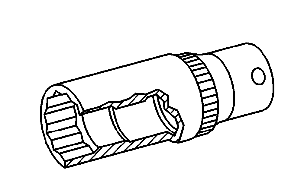
001 589 65 09 00
Socket wrench bit
Odkazované dokumenty
- ad0000p200004a Připojení STAR DIAGNOSIS, načtení chybové paměti
- ad0000p200004a
- ah0000n000101a Upozornění k samopojistným šroubům a maticím
- ah5410p000101a Upozornění k akumulátoru
- ah5410p000101a
- ap4110p4152z Zkontrolovat kloubový hřídel - pružnou kotoučovou spojku na poškození a na deformaci
- ar0060p1000t
- ar0320p100001a Odstranění koroze z klikového hřídele
- ar1530p7100ts Demontáž, montáž startéru
- ar1530p7100tx
- ar2210p1180ts
- ar2700p0270w Naplnit automatickou převodovku olejem
- ar2710p050201ts
- ar2720p010001a Odšroubování, přišroubování měniče momentu u unašeče
- ar2720p050001w Vyjmutí, nasazení měniče momentu
- ar4110p005002t
- ar4110p005007i
- ar4110p005009da
- ar4910p7000ts
- ar5410p0003t Odpojení, připojení ukostřovacího kabelu akumulátoru
- ar5410p0003t
- ar5410p0003ta Odpojení, připojení ukostřovacího kabelu akumulátoru
- ar5410p0003ta
- ar6120p1105t
- ar8840p1000t
- as0000z000501a Nebezpečí úrazu při samovolném rozjetí vozidla při běžícím motoru. Nebezpečí poranění pohmožděním a popálením při výkonech prováděných během startování nebo při běžícím motoru