
P01.10-3216-08
2 | Air cleaner housing | 5 | Steering coupling | 8 | Fuel line | ||
3 | Refrigerant line | 6 | Low-temperature circuit coolant expansion reservoir | 9 | Coolant hose | ||
4 | Coolant hose | 7 | Vacuum line |
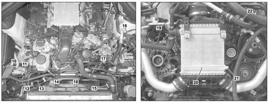
P01.10-3219-08
11 | Coolant hose | 15 | Refrigerant line | 19 | Connecting point for low-temperature circuit coolant expansion reservoir | ||
12 | Coolant hose | 16 | Purge valve | 20 | Charge air cooler | ||
13 | Coolant hose | 18 | Radiator |

P01.10-3220-09
23 | Oil line | 30 | Transverse control arm | 39 | Transfer case | ||
25 | Oil line | 33 | Stiffening plate | 40 | Heat shield | ||
26 | Front axle carrier | 34 | Exhaust pipes with catalytic converters | 42 | Propeller shaft | ||
27 | Bolts | 35 | Rear engine crossmember | 43 | Stiffening plate | ||
28 | Brake caliper | 37 | Stiffening plate | 44 | Switchover valve | ||
29 | Steering knuckle | 38 | Center muffler | 45 | Coolant hose |

46 | Coolant pump |
47 | Coolant hose |
P20.10-2412-11
Warning | Risk of injury to skin or eyes from hydraulic fluid spraying out under pressure.Risk of poisoning from swallowing hydraulic fluid. | Depressurize hydraulic system completely before starting any work on it. Wear protective clothing and safety glasses. | |
Danger | Risk of explosion caused by fuel igniting, risk of poisoning caused by inhaling and swallowing fuel as well as risk of injury to eyes and skin caused by contactwith fuel. | No fires, sparks, open flames or smoking. Pour fuels into suitable and appropriately marked containers only. | |
Danger | Risk of death caused by vehicle slipping or toppling off of the lifting platform. | Align vehicle between vehicle lift columns and position the four support plates at the vehicle lift support points specified by the vehicle manufacturer. | |
Warning | Risk of injury. Skin or eye injuries may result when handling hot or glowing objects. | Wear protective gloves, protective clothing and safety glasses, if necessary. | |
Caution | Risk of injury caused by scraping or cutting body parts on sharp vehicle parts | Always wear protective gloves when working on or near sharp and non-deburred vehicle parts. | |
Topical note | Information on preventing damage to electronic components due to electrostatic discharge | ||
Topical note | Notes on self-locking nuts and bolts | ||
Topical note | Notes on bolted connections with self tapping screws | ||
Topical note | Notes on threaded connections fastened using a tightening angle-based tightening process | ||
Topical note | Notes on avoiding damage through contamination and foreign objects | ||
Notes on AIRmatic | Engine 276.8 in model 251 | ||
Use of engine no. when installing reconditioned engines and factory-new replacement engines or crankcases | |||
Notes on automatic transmission | |||
General information on work on gasoline direct injection system | |||
Notes on repair work on suspension components | |||
Note on calculation of tightening torque when using insertion or socket tools with various effective lengths | |||
| Remove/install | ||
1 | Secure vehicle against rolling away, shift transmission to neutral position and release parking brake | ||
2 | Secure vehicle on vehicle lift | ||
3 | Reduce pressure in air suspension with vehicle diagnosis system | Engine 276.8 in model 251 | |
| |||
4 | Deactivate easy entry/exit feature | Engine 276.8 in model 251 | |
5 | Turn complete wheels on front axle to straight-ahead position and secure steering wheel with holding device | Retainer device | |
6 | Disconnect ground line from battery | ||
7 | Remove lower engine compartment paneling | ||
Installation: Only install lower engine compartment linings once leak test has been completed. | |||
8 | Drain coolant at radiator (18) | ||
9 | Drain coolant from low-temperature circuit | ||
10 | Remove partition wall between wheel wells | ||
11 | Remove water drain above windshield wiper system | ||
12 | Unclip coolant hose (13) on charge air cooler (20) and place to one side | ||
13 | Remove left and right air filter housing (2) | ||
14 | Drain air conditioning system | ||
15 | Disconnect refrigerant line (3) at upper separating point in engine compartment and seal openings with suitable stop plugs | ||
| Compressor oils (specification 362.1) | ||
Installation: | |||
Record plug | |||
16 | Disconnect vacuum line (7) from vacuum pump and place to one side | ||
17 | Relieve fuel pressure over diagnostic socket | ||
Cap on service connection | |||
Pressure hose | |||
18 | Remove fuel line (8) at fuel distributor and seal openings with suitable stop plugs | Union nut, fuel line to fuel distributor | |
Record plug | |||
19 | Remove coolant hose (9) to heater cooler at bulkhead and place to one side | ||
20 | Remove steering coupling (5) at upper steering shaft | ||
| |||
21 | Unclip purge valve (16) at coolant expansion reservoir and place to one side | ||
22 | Disconnect upper coolant hose (4) on cooler (18) | ||
23 | Remove charge air cooler (20) with connected lines and coolant hoses and place to one side | ||
24 | Suction off oil from expansion reservoir of power steering | Hand pump | |
25 | Disconnect hydraulic lines at radiator (18) and seal openings with suitable stop plugs | | |
Record plug | |||
26 | Disconnect engine wiring harness to remove engine | ||
27 | Remove coolant hose (11) at connecting point to charge air cooler circulation pump | ||
28 | Remove coolant hose (12) at connecting point of low-temperature circuit coolant expansion reservoir (19) from low-temperature circuit coolant expansion reservoir (6) | ||
29 | Disconnect coolant hose (47) on connection piece to coolant pump (46) | ||
30 | Remove heat shield (40) at transfer case (39) | ||
31 | Remove refrigerant line (15) at condenser, place to one side and seal openings with suitable stop plugs | ||
| Compressor oils (specification 362.1) | ||
Installation: | |||
Nut/bolt, high-pressure line to fluid reservoir | |||
Record plug | |||
32 | Disconnect lower coolant hose at radiator (18) | ||
33 | Disconnect coolant hose (45) at switchover valve (44) of stationary heater and unclip at longitudinal member | Engine 276.8 in model 251 | |
34 | Remove oil lines (23, 25) at oil cooler and at radiator (18), unclip from blower housing and seal openings with suitable stop plugs and place to one side | ||
Installation: Replace seals and safety clips. | |||
Record plug | |||
35 | Remove upper transverse control arm at steering knuckles (29) | ||
36 | Remove brake calipers (28) with connected lines at brake caliper supports, place to one side and secure against falling down | ||
37 | Remove rpm sensors at steering knuckles (29), unclip from brackets and place to one side | ||
38 | Remove suspension struts at lower transverse control arms (30) | ||
39 | Remove stabilizer bar torsion bar linkage at suspension struts | Nut, torsion bar linkage to front suspension strut | |
40 | Remove exhaust pipes with catalytic converters (34) at separating point from center muffler (38) | ||
41 | Remove propeller shaft (42) at transmission output flange of transfer case (39) and secure against falling down using suitable means | ||
42 | Support front axle carrier (26) with lifting platform and mounting plates and secure entire engine-transmission unit with suitable means against slipping and falling down | ||
| 000 588 03 62 00 Lifting platform | ||
When doing so ensure that mounting plates are evenly aligned. | |||
43 | Remove rear engine crossmember (35) together with stiffening plates (37, 43) | ||
44 | Remove screws of stiffening plates (33) at longitudinal members | Bolt, stiffening plate to longitudinal member | |
45 | Remove screws (27) from longitudinal members | ||
Installation: Replace screws/bolts (27). | |||
46 | Lower engine transmission unit with front axle carrier (26) | ||
| 000 588 03 62 00 Lifting platform | ||
| |||
47 | Install in the reverse order | ||
Concluding tasks | |||
48 | Check transmission oil level and correct if necessary | ||
49 | Check engine oil level and correct if necessary | ||
| |||
50 | Fill steering and bleed | ||
51 | Perform wheel alignment check | ||
Warning | Risk of burn injuries, suffocation and poisoning when working on the exhaust system and the components connected to it. Risk of suffocation and risk of poisoning caused by inhalation of gaseous and solid components of the exhaust. Risk of poisoning caused by skin contact with solid components of the exhaust. | Wear protective clothing and safety glasses. Use the extraction system. Move people out of the hazard area. | |
Warning | Risk of accident from vehicle starting off by itself when engine running. Risk of injury (bruises and burns) resulting from working on the engine while it is being started or when it is running. | Secure vehicle to prevent it from starting off by itself. Wear closed and snug-fitting work clothes. Do not touch hot or rotating parts. | |
52 | Perform engine test run; as part of this check engine and transmission for proper operation and leak tightness |



210 589 00 71 00
Hand pump
129 589 01 21 00
Retainer device
129 589 00 91 00
Record plug
119 589 04 63 00
Pressure hose
Odkazované dokumenty
- ad0000p200004a
- ad0000p200004a Připojení STAR DIAGNOSIS, načtení chybové paměti
- ah0000n000101a Upozornění k samopojistným šroubům a maticím
- ah0000p000701sf Upozornění ke šroubovým spojům se samotvarovatelnými šrouby
- ah0000p001501cw Pokyny pro výpočet utahovacího momentu při použití zasouvacích nebo násuvných nástrojů s různými činnými délkami
- ah0000p002001a Pokyny ke šroubovým spojům, které byly vytvořeny podle postupu utahování s řízeným úhlem otáčení
- ah0000p010001a Pokyny k opravárenským pracím na komponentech podvozku
- ah0000p500001a Upozornění k zamezení poškozením kvůli znečistění a výskytu cizích těles
- ah0110p000101a Manipulace s číslem motoru při montáži výměnných motorů a nových náhradních motorů z výroby, resp. bloků válců
- ah0700p200001a
- ah0700p200001a Všeobecné pokyny k pracím na přímém vstřikování paliva zážehových motorů
- ah2719p000101nkb
- ah2719p000101nkb Upozornění automatické převodovky
- ah3222p100002rt Upozornění k AIRmatic
- ah5400p000101a Upozornění k zamezení poškozením elektronických součástí elektrostatickým výbojem
- ap1800p1811mp Zkontrolovat hladinu motorového oleje olejovou měrkou z výbavy vozidla
- ar0060p0100rt
- ar0100p241002rtc
- ar0703p146001va Snížit tlak paliva pomocí servisního ventilu
- ar0910p1150gqc Demontáž, montáž pláště vzduchového filtru
- ar0941p0001gqc Demontáž, montáž vyrovnávací nádržky nízkoteplotního okruhu
- ar0941p131101al Otevřít a uzavřít spojku
- ar0941p6819gqc Demontáž, montáž vodou chlazeného chladiče plnicího vzduchu
- ar0941p6925rtc Demontáž, montáž oběhového čerpadla pro nízkoteplotní kapalinový okruh
- ar2000p1142gzc Vypuštění, doplnění chladicí kapaliny
- ar2210p1180gzd Demontáž, montáž zadního lůžka motoru, resp. zadního příčníku motoru
- ar2700p0270w Naplnit automatickou převodovku olejem
- ar2710p050103rt Odpojení a připojení potrubí převodového oleje
- ar3225p1017rt Demontáž, montáž pružinové vzpěry vpředu
- ar3310p0100rt
- ar3325p0400rt
- ar4020p0200rt
- ar4110p0050rt
- ar4210p0070rt Demontáž, montáž třmenu kotoučové brzdy přední nápravy
- ar4230p0712rt Demontáž, montáž snímače otáček vpředu vlevo popř. vpravo
- ar4610p8000rt
- ar4630p0010rt
- ar4910p5500gqc Demontáž, montáž katalyzátoru
- ar5410p0003rt Odpojení, připojení ukostřovacího kabelu akumulátoru
- ar6120p1105rt
- ar6230p2400rt
- ar8325p1406rt
- ar8330p1760rt
- as0000z000201a Nebezpečí poranění kůže nebo očí při zacházení s horkými nebo žhavými předměty
- as0000z000501a Nebezpečí úrazu při samovolném rozjetí vozidla při běžícím motoru. Nebezpečí poranění pohmožděním a popálením při výkonech prováděných během startování nebo při běžícím motoru
- as0000z001001a Nebezpečí ohrožení života v případě sesunutí nebo překlopení vozu z dílenského zvedáku
- as0000z001301a Nebezpečí poranění kůže a očí hydraulickou kapalinou vystřikující vlivem vysokého tlaku. Nebezpečí otravy při požití hydraulické kapaliny
- as0000z001701a Nebezpečí poranění řeznými ranami, resp. odřeninami u dílů vozidla s ostrými hranami
- as4700z000101a Nebezpečí výbuchu při vznícení, nebezpečí otravy při vdechnutí a požití paliva inebezpečí úrazu v důsledku přímého doteku kůže a očí s palivem
- as4900z000101a Nebezpečí popálení, udušení a otravy při pracích na výfukovém systému a s ním spojených součástech. Nebezpečí udušení a nebezpečí otravy při vdechnutí plynných a pevných složek výfukových plynů. Nebezpečí otr
- bb0040p036201a Kompresorové oleje (specifikace 362.1)
- ws0100p0091a