
D88.30-1189-09
1 | Front module | 5 | Engine hood cable | 9 | Circuit | ||
2 | Air cleaner housing | 6 | Engine hood catch | 10 | Spray nozzle hose | ||
3 | Air intake pipe | 7 | Spray nozzle hose | 11 | Charge air hose | ||
4 | Air duct insert | 8 | Spray nozzle | 12 | Charge air cooler |

D88.30-1190-09
1 | Front module | 16 | Air duct insert | 20 | Refrigerant line separating point | ||
13 | Fender | 17 | Screw | 21 | Nut | ||
14 | Marking | 18 | Bracket | 22 | Washer | ||
15 | Screw | 19 | Screw | 23 | Bolts |

Shown on model 906 with transmission 722.9 with oil cooler automatic transmission integrated in the radiator |
24 | Upper return line |
25 | Rear return line |
27 | Front feed line |
28 | Rear feed line |
29 | Front return line |
D27.55-1119-12

Shown on model 906 with transmission 722.9 without oil cooler automatic transmission integrated in the radiator |
25 | Rear return line |
27 | Front feed line |
28 | Rear feed line |
29 | Front return line |
D27.55-1120-12
Warning | Risk of accident from vehicle starting off by itself when engine running. Risk of injury (bruises and burns) resulting from working on the engine while it is being started or when it is running. | Secure vehicle to prevent it from starting off by itself. Wear closed and snug-fitting work clothes. Do not touch hot or rotating parts. | |
Warning | Risk of burns and scalding when handling hot fluids and components they come into contact with. Risk of injury to skin and eyes when handling hot fluids. | Wear protective gloves, protective clothing and safety glasses, if necessary. Pour hot fluids in suitable containers only. | |
Notes on automatic transmission | Model 906 with engine 642.896 with transmission 722.9 | ||
| Remove/install | ||
1 | Drain air conditioning system |
| |
Model 906 with engine 642.896/898/992/993 | |||
2 | Remove transmitter key | ||
3 | Remove front bumper |
| |
Model 906 with engine 642.896/898 | |||
Model 906 with engine 642.896/898/992/993 | |||
4 | Remove air duct inserts (4) | ||
5 | Remove air intake pipe (3) | ||
6 | Pull air filter housing (2) out of mounts on front module (1) (arrows) | ||
7 | Drain off coolant | ||
Danger | Risk of death when working on component parts and systems with U >= 30 V alternating voltage (AC) or U >= 60 V direct voltage (DC) | Do not touch damaged or defective live component parts and lines or non-insulated electrical connections and lines. | |
Danger | Risk of explosion/risk of fire caused by highly flammable materials in the vicinity of damaged xenon bulbs. Risk of injury caused by UV light, hot components on xenon headlamps and glass splinters produced by bursting xenon bulbs. Risk of poisoning caused by inhalation of mercury vapors and by swallowing of/skin contact with toxic salts and mercury compounds. | Do not touch parts conducting high voltage. Persons with active electronic implants (e.g. cardiac pacemakers) must never work on xenon headlamps. Switch off the entire lighting system. Wear insulated safety shoes, safety glasses and protective gloves. Remove highly inflammable materials from the danger zone. Ensure sufficient ventilation in the working area. | |
8 | Disconnect electrical lines to remove front module (1) | ||
9 | Unhook engine hood release cable (5) from engine hood catch (6) and lay down to side | ||
10 | Disconnect coolant hoses from cooler | ||
M61 | |||
11 | Disconnect charge air hose (11) from charge air cooler (12) | ||
12 | Unscrew nut (21) from refrigerant line separating point (20) | Model 906 with engine 642.896/898/992/993 | |
Nut, refrigerant lines to expansion valve | |||
13 | Disconnect refrigerant lines from condenser | Model 906 with engine 642.896/898/992/993 | |
| Compressor oils (specification 362.0) | ||
Installation: Replace sealing rings and coat with compressor oil. | |||
Nut, refrigerant lines to condenser | |||
14 | Immediately plug connections with clean stop plug | Model 906 with engine 642.896/898/992/993 | |
Record plug | |||
Warning | Risk of injury to skin or eyes from hydraulic fluid spraying out under pressure.Risk of poisoning from swallowing hydraulic fluid. | Depressurize hydraulic system completely before starting any work on it. Wear protective clothing and safety glasses. | |
15 | Disconnect hydraulic lines from radiator of power steering |
| |
Model 906 up to 12/2/11 with engine 642.896/898/992/993 | |||
Record plug | |||
Hand pump | |||
16 | Disconnect upper return line (24) from cooler | Model 906 with engine 642.896 with transmission 722.902 | |
Record plug | |||
17.1 | Disconnect rear return line (25) from cooler | Model 906 with engine 642.896 with transmission 722.902 | |
Record plug | |||
17.2 | Disconnect front return line (29) from rear return line (25) | Model 906 with engine 642.896 with transmission 722.902 | |
Record plug | |||
18 | Disconnect front return line (29) from upper return line (24) | Model 906 with engine 642.896 with transmission 722.902 | |
Record plug | |||
19 | Disconnect front feed line (27) from rear feed line (28) |
| |
Record plug | |||
20 | Clamp off spray nozzle hose (10) with clamp (9) | Model 906 with engine 642.896/898/992/993 | |
Clamp | |||
21.1 | Disconnect spray nozzle hose (7) from spray nozzles (8) | Model 906 with engine 642.896/898/992/993 | |
Installation: Check sealing rings for damage; replace if necessary. | |||
21.2 | Unclip spray nozzles (8) from headlamps | Model 906 with engine 642.896/898/992/993 | |
22 | Immediately plug connections with clean stop plug | Model 906 with engine 642.896/898/992/993 | |
Record plug | |||
23 | Unscrew bolts (19) on left and right side of vehicle | Bolt, module carrier to upper and lower A-pillar inner section | |
24 | Unscrew bolts (17) on left and right side of vehicle and unclip bracket (18) on fender (13) | ||
25 | Insert subbases (22) on left and right side of vehicle between front module (1) and longitudinal member | Washer | |
26 | Mark (14) fenders (13) on both sides to indicate installation position of front module (1) | Model 906 with engine 642.896/898/992/993 | |
27 | Unscrew bolts (15) on left and right side of vehicle | M61 | |
28 | Unscrew bolts (23) on left and right side of vehicle | Bolt, module carrier to longitudinal member bracket | |
29 | Fold air duct insert (16) toward inside | ||
30 | Lift out front module (1) with aid of helper | Installation: Position front module (1) on vehicle so that bolt holes for bolts (15) in front module (1) are centered in relation to the threaded holes of fender (13). A uniform gap should be present between the fenders (13) and lamp units, if required, align lamp units in relation to fenders (13). | |
31 | Install assembly device on front module (1) | ||
Assembly device | |||
Mounting plates | |||
32 | Install in the reverse order | ||
33 | Fill power steering pump and bleed | ||
34 | Check oil level in A/T and correct if necessary |
| |
Model 906 with engine 642.896 with transmission 722.9 | |||
Model 906.1/2/6/7 with engine 642.896 with transmission 722.6 | |||
Model 906 with engine 642.896/898/992/993 with transmission 722.683Automatic transmission fluid ATF | |||
Funnel | |||
Model 906 with engine 642.896/898/992/993 with transmission 722.6 | |||
Hand pump | |||
35 | Check feed lines (27, 28) or return lines (24, 25, 29) for leakage when engine is running. | Model 906 with engine 642.896 with transmission 722.9 | |
36 | Check headlamp adjustment and correct if necessary | After aligning lamp units in relation to fenders (13). | |
| Model 906 with engine 642.896/898/992/993 | ||
| Model 906 with engine 642.896/898/992/993 |
Air conditioning |
Number | Designation | Model 906 up to 13.04.14 with code HK4, IR4, ZL3 (with condenser module on roof (KONVEKTA)) | Model 906 as of 01.01.16 with code HK4, ZL3, except code IR4 (with condenser module on roof (MAHLE)) | |
BA83.30-N-1001-01F | Nut, refrigerant lines to expansion valve | Nm | - | 8 |
Air conditioning |
Number | Designation | Model 906 up to 13.04.14 with code HK4, IR4, ZL3 (with condenser module on roof (KONVEKTA)) | Model 906 as of 01.01.16 with code HK4, ZL3, except code IR4 (with condenser module on roof (MAHLE)) | |
BA83.30-N-1005-01F | Nut, refrigerant lines to condenser | Nm | - | 8 |
Automatic transmission |
Number | Designation | Transmission 722.683/684/685/686 | |||
BF27.00-N-1001-01A | Automatic transmission fluid ATF | Filling capacity - complete refill | Liter | 7,1 | |
Filling capacity - oil change | Liter | 7,1 | |||
Filling capacity, transmission oil change | with torque converter | Liter | 7,1 | ||
Filling capacity, transmission oil change | without torque converter | Liter | 5,5 | ||
Sheet | - | ||||
Sheet | |||||
Sheet | - | ||||
Sheet | - | ||||
Sheet | - | ||||
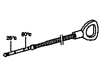



140 589 15 21 00
Dipstick
210 589 00 71 00
Hand pump
639 589 02 62 00
Assembly device
000 589 40 37 00
Clamp



129 589 00 91 00
Record plug
906 589 02 62 00
Mounting plates
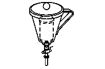
126 589 12 63 00
Funnel
906 589 00 31 00
Washer
เอกสารที่อ้างถึง
- ah2719p000101nkb
- ah2719p000101nkb
- ap8210d8260a
- ap8210d8260b
- ar0941d8619m
- ar2000d1140sd
- ar2020d386509sd
- ar2700d0101we
- ar2700d027001a
- ar2700d0270we
- ar2710d050103we
- ar2755d010001us
- ar4625d302001sd
- ar4625d302001se
- ar4630s0010s
- ar8330d1760d
- ar8330d1760we
- ar8820d2000m
- ar8820d2000sd
- ar8820d2000se
- ar8830d106401sd
- ar8830d106402sd
- as0000z000501a
- as0000z001301a
- as0000z003301a
- as0000z003501a
- as8210z000101a
- bb0040p036200a