

D26.50-0033-01
D26.50-0034-01
1 Clamp transmission main shaft in a clamping device or a vise with protective jaws.
2 Push on needle bearing (32).
Grease needle bearing.
3 Push on reverse gear (33).


D26.50-0031-01
4 Install sliding block (36), compression springs (38) and balls (37) in synchronizer body (39) and push on sliding sleeve (35).
5 Install synchronizer body (39) with sliding sleeve (35).
The tip (arrow) of the sliding sleeve (35) must point upwards.
D26.50-0035-01


D26.50-0074-01
D26.50-0030-01
6 Install locking ring (40).
Replace locking ring.
Do not overstretch locking ring when installing otherwise the gear wheels will not fit
7 Push on inner synchronizer ring (46) and synchronizer cone (41).


D26.50-0036-01
D26.50-0028-01
8 Push on needle bearing (42) and 5th gear wheel (43).
Grease needle bearing.
9 Push on thrust washer (44).


D26.50-0026-01
D26.50-0027-01
10 As of transmission end no. 004088
Install locking ring (45)
No locking ring is installed on transmissions with a lower transmission end no.
11 Rotate transmission main shaft.
12 Push on needle bearing (30).
Grease needle bearing.


D26.50-0075-01
D26.50-0025-01
13 Push on 1st gear (29).
14 Push on synchronizer cone (28), inner synchronizer ring (27) and synchronizer cone (26).
Lubricate synchronizer cone and inner synchronizer ring.


D26.50-0077-01
D26.50-0102-01
15 Install sliding block (24), compression springs (23) and balls (22) in synchronizer body (25) and push on sliding sleeve (21).
The asymmetric tip (arrow) of the sliding sleeve must point towards the higher collar of the synchronizer body (arrow). (Also refer to sectional drawing)
Synchronizer body (25):
a: Previous version (up to transmission end no. 0329833).
b: New version (transmission end no. 0329834 - 0330009 and as of end no. 0336317).


D26.50-0021-01
D26.50-0038-01
16 Push on synchronizer body with sliding sleeve (21).
The asymmetric tip (arrow) of the sliding sleeve (21) must point upwards (2nd gear).
17 Install locking ring (17).
Replace locking ring.
Do not overstretch locking ring when installing otherwise the gear wheels will not fit.

D26.50-0019-01
D26.50-0020-01
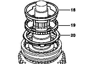
18 Push on synchronizer cone (18), inner synchronizer ring (19) and synchronizer cone (20).
Lubricate synchronizer cone and inner synchronizer ring.
19 Push on needle bearing (16) and 2nd gear wheel (15).
Grease needle bearing.


D26.50-0017-01
D26.50-0018-01
20 Push on thrust washer (14) and drive on using a suitable drift punch.
21 Install locking ring (13).
Replace locking ring. The locking ring must not be bent when tensioning apart otherwise the gear wheels will not fit.


D26.50-0079-01
D26.50-0016-01
22 Push on needle bearing (12) and 3rd gear wheel (11).
Grease needle bearing.
23 Push on synchronizer cone (47).


D26.50-0015-01
24 Push on inner synchronizer ring (10).
Lubricate synchronizer cone.
25 Install sliding block (6), compression springs (8) and balls (7) in synchronizer body (9) and push on sliding sleeve (5).
D26.50-0099-01


D26.50-0013-01
D26.50-0100-01
The projecting tip (arrow) of the sliding sleeve (5) must point towards the narrow (arrow) of the synchronizer body (9).
26 Push on synchronizer body with sliding sleeve (5).
The synchronizer body must point upwards together with the projecting tip (arrow).


D26.50-0011-01
D26.50-0012-01
27 Install locking ring (4).
Replace locking ring. Do not overstretch locking ring when installing otherwise the gears will not fit.
28 Push on inner synchronizer ring (3) and 4th gear synchronizer cone (2).
Lubricate inner synchronizer ring and synchronizer cone.

D26.50-0010-01
29 Push on needle bearing (1).
Grease needle bearing.
30 Unclamp transmission main shaft.