Commercially available tools


D26.50-0011-01
D26.50-0010-01
1 Clamp transmission main shaft in a clamping device or in a vise with protective jaws.
2 Remove needle bearing (1).
3 Remove 4th gear synchronizer cone (2) and inner synchronizer ring (3).


D26.50-0013-01
D26.50-0012-01
4 Remove locking ring (4)
5 Remove synchronizer body with sliding sleeve (5).


D26.50-0015-01
D26.50-0099-01
6 Push sliding sleeve (5) off synchronizer body and remove sliding block (6), compression springs (8) and balls (7).
The balls and sliding block remain under spring pressure.
Cover synchronizing device with a suitable cloth when dismantling.
7 Remove inner synchronizer ring (10).


D26.50-0016-01
D26.50-0079-01
8 Remove synchronizer cone (47)
9 Remove 3rd gear wheel (11) needle bearing (12).


D26.50-0103-01
D26.50-0017-01
10 Remove locking ring (13).
11 Remove thrust washer (14)
Remove seized thrust washers with a suitable puller together with gearshift (15)
Do not install puller on shift teeth (arrow).

D26.50-0020-01
D26.50-0019-01
12 Remove 2nd gear wheel (15) and needle bearing (16).
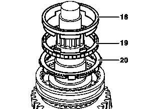
13 Remove synchronizer cone (20), inner synchronizer ring (19) and synchronizer cone (18).

D26.50-0022-01
D26.50-0021-01
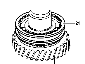
14 Remove locking ring (17).
15 Remove synchronizer body together with sliding sleeve (21).


D26.50-0075-01
D26.50-0076-01
16 Push sliding sleeve (21) off synchronizer body (25) and remove sliding block (24), compression springs (23) and balls (22).
Balls remain under spring pressure. Cover synchronizing device with a suitable cloth when dismantling.
17 Remove synchronizer cone (26), inner synchronizer ring (27) and synchronizer cone (28).


D26.50-0026-01
D26.50-0025-01
18 Remove 1st gear wheel (29).
19 Remove needle bearing (30).
20 Rotate transmission main shaft.


D26.50-0028-01
D26.50-0027-01
21 Up to transmission end no. 004087
Remove thrust washer (44)
As of transmission end no. 004088
Remove locking ring (45) and thrust washer (44).
22 Remove 5th gear wheel (43) and needle bearing (42).


D26.50-0030-01
D26.50-0074-01
23 Remove synchronizer cone (41) and inner synchronizer ring (46).
24 Remove locking ring (40) and remove synchronizer body together with sliding sleeve (35).


D26.50-0033-01
D26.50-0031-01
25 Push sliding sleeve (35) from synchronizer body (39) and remove sliding block (36), compression springs (38) and balls (37).
Balls remain under spring pressure. Cover synchronizing device with a suitable cloth when dismantling.
26 Remove reverse gear (33)

D26.50-0034-01
27 Remove needle bearing (32).