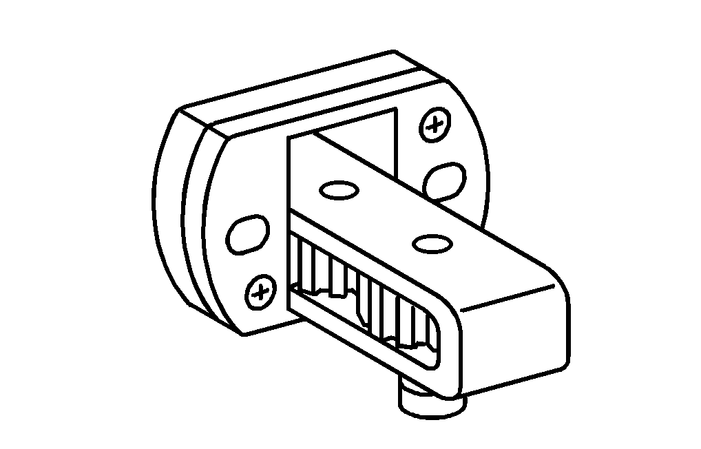


904 589 04 63 00
Turning device
936 589 00 23 00
Template
936 589 00 15 00
Drift

1 | Turn flywheel (1) or ring gear carrier using turning device until the marking (arrow B) on the flywheel (1) or ring gear carrier lines up with the casting edge (arrow A) of the flywheel housing (2). |
W05.10-1017-02

Use the set of bolts for the diesel engine (E).
3 | Template |
3.1 | Bolt, intake camshaft |
3.2 | Bolt, exhaust camshaft |
E | Set of bolts for diesel engine |
W05.10-1076-05

W05.10-1022-08
2 | Attach template (3) to the rocker arm frame (4). |
3 | Check position of the bore (arrow C) on gear (5) of the intake camshaft and position of the bore (arrow D) on the gear (6) of the exhaust camshaft. |
The bores (arrow C, D) must be in a "12-o'clock position" and the lugs of the template (3) must face the center of the bores (arrows C, D), if necessary turn engine through 360° again (one turn of the engine). |

4 | Disconnect electrical connection (7) on crankshaft position sensor (B600). |
5 | Remove screw/bolt for the crankshaft position sensor (B600) and pull the crankshaft position sensor (B600) out of the flywheel housing (2). |
6 | Insert drift (8) into flywheel housing (2) and lock flywheel (1) or ring gear carrier in place. |
The pin in the drift (8) must be seated in the bore (arrow E) in the flywheel (1) or the ring gear carrier. |
W05.10-1019-06