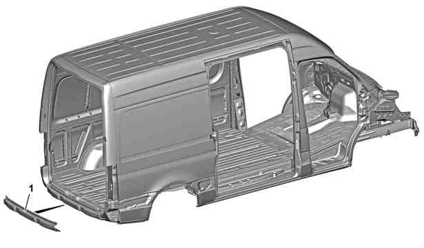
1 | Crossmember |
D64.20-0088-05

D60.00-A000-09
Shown on model 907 with code Q50 (Removable ball head for trailer coupling) |
2 | Rear-end doors | 6 | Left lock striker | |
3 | Bumper | 7 | Right guide pin | |
4 | Trailer hitch | 8 | Cover | |
5 | Frame seal |

D60.00-A001-09
Shown on model 907 with code Q50 (Removable ball head for trailer coupling) |
4 | Trailer hitch | 9 | Electrical wiring harness |
Danger | Risk of death when working on component parts and systems with U >= 30 V alternating voltage (AC) or U >= 60 V direct voltage (DC) | Do not touch damaged or defective live component parts and lines or non-insulated electrical connections and lines.Model 910.6 with engine 780.703 | |
Danger | Risk of death caused by vehicle slipping or toppling off of the lifting platform. | Align vehicle between vehicle lift columns and position the four support plates at the vehicle lift support points specified by the vehicle manufacturer. | |
Topical note | General information on handling vehicles with high-voltage on-board electrical system and/or lithium-ion battery and/or gaseous-fuel drive system | Model 910.6 with engine 780.703 | |
Topical note | Notes on carrying out repair work in the vehicle interior | ||
| Remove/install | ||
1 | Remove rear-end doors (2). | ||
2 | Remove bumper (3). |
| |
Model 907.6/7, 910.6 | |||
3.1 | Remove sprung step. | Model 907.6/7, 910.6 | |
To do so, counterhold nuts and remove screws/bolts of the sprung step. | |||
Helper required. | |||
Screw/nut, sprung running board to longitudinal member | |||
3.2 | Remove step. | Model 907.6/7, 910.6 | |
To do so, counterhold nuts and remove screws/bolts of the step. | |||
Helper required. | |||
Screw/nut, running board to longitudinal member | |||
4 | Remove rear towing eye. | Model 907.6 | |
To do so, unscrew screws/bolts of the towing eye. | |||
Bolt, towing eye to longitudinal member | |||
5 | Remove trailer hitch (4). |
| |
6 | Unhook decoupling elements of the exhaust system from the body at the rear. | Model 907.6/7 | |
7 | Remove spare wheel holder under frame end. | Model 907.6/7, 910.6 | |
8 | Remove electrical wiring harness (9) from the crossmember (1) and position outside the working area. | ||
9 | Remove sealing frame (5) in repair area and position outside the working area. | ||
10 | Remove cover (8) for rear entrance. | ||
In the process, the left lock striker (6) and the right guide pin (7) are removed. | |||
11 | Install in the reverse order. |
Powiązane dokumenty
- ah0000z030001a Ogólne wskazówki dotyczące pojazdów z instalacją wysokiego napięcia i/lub akumulatorem litowo-jonowym i/lub gazowym systemem napędu oraz osobistego wyposażenia ochronnego
- ah6800n000101s Wskazówki dotyczące wykonywania prac naprawczych we wnętrzu pojazdu
- ar3110d8000ts
- ar6830d3520ts
- ar7220d1901ts
- ar8820d2200ts
- ar8820d2200tsb
- as0000z001001a Zagrożenie życia na skutek ześlizgnięcia lub spadnięcia pojazdu z podnośnika.
- as0000z003501a Zagrożenie życia podczas prac przy elementach i systemach U >=30 V napięcie zmienne (AC) bądź U >=60 V napięcie zmienne