
P33.10-2274-09
1 Suspension strut
1b Screw
2 Electrical connector
3 Brake hose
31 Front axle carrier
Y10 SPS [PML] solenoid valve
4 High pressure expansion hose
5 Return hose
6 Steering coupling
7 Electrical connector

P33.10-2275-06
1a Screw
5 Return hose
8 Diagonal strut
9 Separation point
31 Front axle carrier
| Remove/install | ||
| Notes on self-locking nuts and bolts | ||
| If there is visible damage, e.g. crack formation or deformation of the front axle carrier, these parts must be replaced | ||
Installation | Only tighten nuts and bolts of chassis components when vehicle is in a ready-to-drive condition. | ||
1 | Deactivate easy entry/exit function for driver seat and steering wheel | Vehicles with code 275, Memory package (driver seat, steering column, mirrors) | |
Otherwise the driver seat and steering wheel move into a different position if the driver door is opened or closed for example. The upper frame may be damaged when the holding device is installed. | |||
Deactivation ensues via buttons on the steering wheel in the "Comfort" menu of the multifunction display. | |||
2 | Move out or pull out adjustable steering column completely | Needed for separating the steering coupling (6). | |
3 | Move front wheels to straight-ahead position and secure steering wheel. | On a disengaged steering coupling (6) the steering wheel should not be turned because the spiral contact coil will be destroyed. | |
| |||
4 | Extract oil from power steering expansion reservoir | | |
5 | Disconnect high-pressure expansion hose (4) from power steering pump | Plug openings. | |
Installation: Replace sealing rings. | |||
| |||
| |||
| |||
| |||
6 | Detach suspension struts (1) from suspension strut towers | Vehicles without code P98 Black Series | |
Vehicles with code P98 Black Series | |||
7 | Mount engine carrier bracket, raise engine | Vehicles without code P98 Black Series | |
Engine hoist | |||
Vehicles with code P98 Black Series | |||
If necessary, detach air filter housing. | |||
8 | Remove the front wheels | ||
| Remove/install wheels, rotate if necessary | ||
9 | Installing protective washers to protect brake disk dust shields | ||
| |||
10 | Disconnect electrical connector(s) on brake lining (s) contact sensor (s) | ||
| Notes on installing brake pad wear sensor contact sensors | ||
11 | Disconnect electrical connectors (2) from rpm sensor | ||
12 | Disconnect electrical connector from front axle sensor for headlamp range adjustment and detach linkage | Vehicles with code 614 bi-xenon headlamp unit or code 615 bi-xenon headlamp unit with integrated curve illumination except vehicles with code P98 Black Series | |
13 | Unscrew brake lines from brake hoses (3) and seal openings | Seal line connections immediately. The brake fluid expansion reservoir must not run completely empty. | |
14 | Detach front diagonal struts (8) | 209.377 with code P98 Black Series, model 209.4 | |
Installation: The bolts of the diagonal struts (8) may only be tightened when the vehicle is standing with its wheels on the ground. | |||
| |||
15 | Remove the bolts (1a) of the engine mounts from the front axle carrier (31) | Engine 112, 113 | |
Engine 156 | |||
Engine 271 | |||
Engine 272, 273 | |||
Engine 612 | |||
Engine 642 | |||
Engine 646 | |||
16 | Detach return hose (5) from front separation point (9) | ||
17 | Remove heat shield upstream of steering coupling (6) | ||
18 | Disconnect steering coupling (6) | ||
19 | Separate electrical connector (7) on SPS solenoid valve PML (Y10) and unclip from the retaining clamps on the front axle carrier (31) | ||
20 | Prop front axle carrier (31) | ||
21 | Remove bolts (1b) from longitudinal members and lower the front axle | Installation: Replace bolts (1b). | |
| |||
22 | Install in the reverse order | ||
23 | Fill power steering pump and bleed | ||
24 | Perform a wheel alignment check |
Power steering pump
Number | Designation | Model 209 | Model | Model 209 | ||
BA46.30-P-1002-01D | Connection fitting, high-pressure expansion hose/line to power steering pump | Nm | 40 | 40 | - | |
BA46.30-P-1003-01D | Banjo bolt, high pressure expansion hose to power steering pump | Nm | - | 40 | 45 | |
Power steering pump
Number | Designation | Engine | |||
BA46.30-P-1006-01K | Banjo bolt, high pressure expansion hose to power steering pump | Nm | 45 | ||
Frame floor assembly
Number | Designation | Model | Model | |
BA61.10-P-1011-01C | Self-locking bolt, front diagonal strut to frame floor/front axle carrier | Nm | 80 | 80 |
Front axle carrier



129 589 00 91 00
Holding device
Set of stop plugs
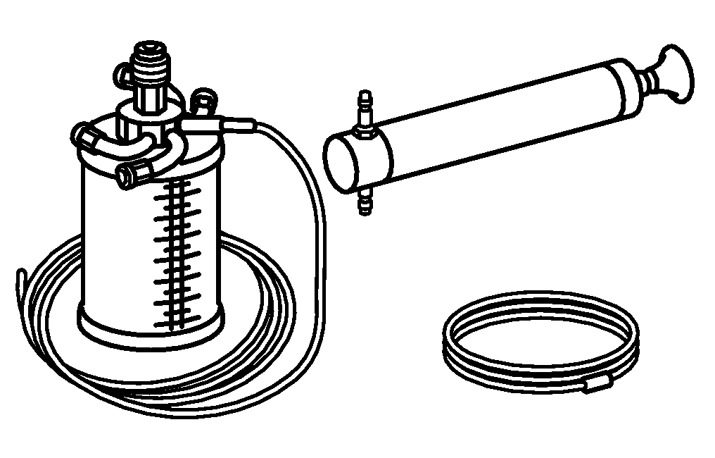
Hand pump
Guard plate
210 589 00 71 00
129 589 01 21 00
220 589 01 31 00

Engine lifting fixture
240 589 00 61 00
Powiązane dokumenty
- ah0000n000101a Wskazówki dotyczące samozabezpieczających śrub i nakrętek
- ah4210p000301a Wskazówki dotyczące montażu czujników stykowych wskaźnika zużycia okładzin hamulcowych
- ap4010p4050z Demontaż i montaż kół, w razie potrzeby przełożenie
- ar2210p1100p Demontaż i montaż łóż silnika
- ar2210p1100pi Demontaż i montaż łóż silnika
- ar2210p1100pv Demontaż i montaż łóż silnika
- ar2210p1100qb Demontaż i montaż łóż silnika
- ar2210p1100qk Demontaż i montaż łóż silnika
- ar2210p1260hb Demontaż i montaż łóż silnika i/lub wsporników silnika z przodu
- ar2210p1260qmg Demontaż i montaż łóż silnika i/lub wsporników silnika z przodu
- ar3225p1017p Demontaż i montaż przednich kolumn zawieszenia
- ar3225p1017qbs
- ar3310p010001p Zakładanie jarzma nośnego silnika, podnoszenie silnika
- ar3310p010003p Podpieranie wspornika osi przedniej za pomocą podnośnika montażowego lub kanałowego
- ar3310p0105qbs
- ar4020p0200p Przeprowadzanie pomiarów podwozia
- ar4200p010001a Zamontowanie osłony zabezpieczającej na osłonach tarcz hamulcowych
- ar4210p0013p Wymiana elastycznych przewodów hamulcowych
- ar4610p8000p Demontaż i montaż sprzęgła przekładni kierowniczej
- ar4630p0010p Napełnij i odpowietrz pompę wspomaganej przekładni kierowniczej.
- ar8210p4083q