AR26.50-S-0419A | Disassembling and assembling output shaft | 27.2.12 |
ENGINE 111.948 /978, 601.942 /970 in MODEL 638 except CODE (G40) Automatic transmission

S26.50-3011-09
1 Output shaft (complete)
2 Clamping bolt
3 Ball bearing
4 Adjustment shims
5 Fixed gear (5th gear)
6 Fixed gear (4th gear)
13 Synchronizer ring (1st/2nd gear)
14 Shift mechanism (1st/2nd gear)
15 Roller bearing
16 Gearwheel (1st gear)
17 Output shaft
7 Fixed gear (3rd gear)
8 Needle roller bearing
9 Bearing sleeve
10 Gearwheel (2nd gear)
11 Friction ring (1st/2nd gear)
12 Cone ring (1st/2nd gear)
| Disassemble | ||
| A press with at least 25t is required for the operations described below. | Workshop press gotis://G_58.2_01.0 | |
1 | Disassemble transmission | ||
2 | Unscrew rigging screw (2) | ||
3 | Press off ball bearing (3) and fixed gears (5, 6) | Do not mix up the shims (4) with the shims of the drive shaft. | |
Thrust piece | |||
| Removal plate | ||
4 | Engage 1st gear at shift mechanism (14) and place removal plate between gearwheel (10) and sliding sleeve of shift mechanism | ||
| Removal plate | ||
5 | Insert thrust sleeve, press off fixed gear (7) and gearwheel (10) and remove needle roller bearing (8) | Thrust sleeve | |
6 | Engage neutral at shift mechanism (14) | ||
7 | Press off bushing (9), shift mechanism (14) and gearwheel (16) | Thrust sleeve | |
| Removal plate | ||
8 | Disassemble shift mechanism (14) | ||
9 | Remove roller bearing (15) | ||
| Checking | ||
10 | Check wear of the synchronizer rings (13). | Fit a new friction ring (11), cone ring (12) and synchronizer ring (13) if necessary. | |
Feeler gauge | |||
11 | Check output shaft (17) and holes of fixed gears (5, 6, 7) for wear | Replace the parts if necessary. | |
| Assemble | ||
| Apply a thin coating of transmission oil to all bearings before installation | ||
12 | Insert roller bearing (15) | The smaller collar of the roller bearing (15) must face the gearwheel (16). | |
13 | Insert gearwheel (16) | ||
14 | Insert roller bearing (15) | The smaller collar of the roller bearing (15) must face the gearwheel (16). | |
15 | Insert friction ring (11) | ||
16 | Insert cone ring (12) | The guides of the cone ring (12) must engage in the cutouts in the gearwheel (16). | |
17 | Insert synchronizer ring (13) | The guides of the friction ring (12) must engage in the cutouts in the synchronizer ring (13). | |
18 | Insert synchronizer body of shift mechanism (14) with collar pointing upwards and press on | The guides of the synchronizer ring (13) must engage in the cutouts in the synchronizer body. | |
Press-in sleeve | |||
19 | Assemble shift mechanism (14) of 1st/2nd gear | ||
20 | Insert synchronizer ring (13) | The guides of the synchronizer ring (13) must engage in the cutouts in the synchronizer body. | |
21 | Insert cone ring (12) | ||
22 | Insert friction ring (11) | The guides of the friction ring (11) must engage in the cutouts in the synchronizer ring (13). | |
23 | Press on bushing (9) as far as axial stop | Press-in sleeve | |
24 | Insert needle roller bearing (8) and gearwheel (10) | The guides of the cone ring (12) must engage in the cutouts in the gearwheel (10). | |
25 | Press on fixed gear (7) with collar pointing upwards as far as axial stop | When pressing on, push the gearwheel (10) down in order to prevent it from jumping out of the guides. | |
Press-in sleeve | |||
26 | Press on fixed gear (6) with collar pointing downwards as far as axial stop | Press-in sleeve | |
27 | Press on fixed gear (5) with collar pointing upwards as far as axial stop | Press-in sleeve | |
28 | Insert removed shims (4) | Do not mix up the shims (4) with the shims of the drive shaft. | |
29 | Press on ball bearing (3) with groove pointing upwards | ||
30 | Screw in rigging screw (2) | Coat the thread with thread locking compound. | |
Engine 111 | |||
Engine 601 | |||
Loctite 243 | |||
31 | Assemble transmission |
Test specifications for gear set
Number | Designation | Model | |
BE26.50-N-1001-01E | Wear limit between synchronizer ring and gearwheel | mm | 0.8 |
Gear set, shafts
Number | Designation | Model 638 with engine 111.948/978 | |
BA26.50-N-1003-01E | Clamping screw to output shaft | Nm | 95 |
Gear set, shafts
Number | Designation | Model 638 with engine 601.942/970 | |
BA26.50-N-1003-01G | Clamping screw to output shaft | Nm | 95 |


638 589 01 35 00
Press-in sleeve
Thrust piece
Thrust sleeve
Press-in sleeve
638 589 00 35 00
638 589 02 35 00
638 589 03 35 00

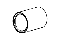
638 589 04 35 00
638 589 05 35 00
Press-in sleeve
Press-in sleeve
Repair materials
Number | Designation | Order number |
BR00.45-Z-1133-02A | Loctite 243 | A 613 989 09 71 |