P14.20-2367-09
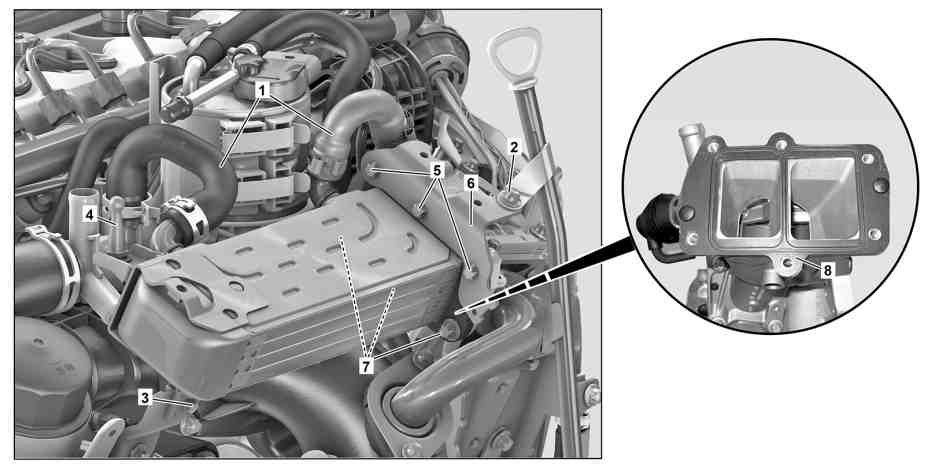
1 | Coolant hose | 4 | Ball stud | 7 | Screw/bolt | ||
2 | Screw/bolt | 5 | Screw/bolt | 8 | Sealing ring | ||
3 | Screw/bolt | 6 | Bracket |
Danger ! | Risk of injury. Skin or eye injuries may result when handling hot or glowing objects. | Wear protective gloves, protective clothing and safety glasses, if necessary. | |
Danger ! | Risk of injury to skin and eyes suffering scalding from contact with hot coolantspray. Risk of poisoning from swallowing coolant. | Do not open cooling system unless coolant temperature is below 90 °C. Open cap slowly and release the pressure. Do not pour coolant into beverage containers. | |
| Notes on avoiding damage through contamination and foreign objects | ||
| Notes on coolant | ||
| Remove/install | ||
1 | Remove vacuum reservoir | ||
2 | Clamp off coolant hoses (1) on exhaust gas recirculation cooler using a clamp | Clamp | |
3 | Detach coolant hoses (1) at the exhaust gas recirculation cooler | Check condition of coolant hoses (1) and clamps for damage; replace if necessary. | |
4 | Remove screw/bolt (2) for guide tube on holder | Bolt for oil dipstick guide tube fastening | |
5 | Remove screw/bolt (3) and ball stud (4) on exhaust gas recirculation cooler | Bolt, support brace for vacuum reservoir and exhaust heat exchanger to Y-support brace | |
Bolt, exhaust heat exchanger support to exhaust heat exchanger | |||
6 | Detach fuel filter with attached fuel lines and place to one side | ||
| |||
7 | Remove screw/bolts (5) and bracket (6) | ||
8 | Remove screw/bolts (7) and exhaust gas recirculation cooler | Installation: Replace sealing ring (8). | |
Use magnetic rod for better removal of the screw/bolts (7). | |||
Bolt, exhaust heat exchanger to valve housing | |||
9 | Install in the reverse order | ||
| Check | ||
10 | Check engine cooling system for leaktightness | ||
Danger ! | Risk of accident from vehicle starting off by itself when engine running. Risk of injury (bruises and burns) resulting from working on the engine while it is being started or when it is running. | Secure vehicle to prevent it from starting off by itself. Wear closed and snug-fitting work clothes. Do not touch hot or rotating parts. | |
11 | Carry out an engine test run and check exhaust recycle plant for leaktightness |

000 589 40 37 00
Clamp
Powiązane dokumenty
- ah0000p500001a Wskazówki dotyczące zapobiegania uszkodzeniom na skutek zabrudzeń i ciał obcych
- ah2000n208001a Wskazówki dotyczące płynu chłodzącego
- ap4720p0780ewd Wymiana filtra paliwa
- ar0709p0001olf
- ar2000p1010lf Sprawdzanie szczelności układu chłodzenia
- as0000z000201a Niebezpieczeństwo zranienia skóry i oczy na skutek kontaktu z gorącymi lub żarzącymi się przedmiotami
- as0000z000501a Niebezpieczeństwo wypadku na skutek samoczynnego ruszenia przy pracującym silniku. Niebezpieczeństwo obrażeń na skutek zmiażdżenia lub poparzenia przy wykonywaniu czynności podczas rozruchu lub przy pracującym silniku.
- as2000z000101a Niebezpieczeństwo zranienia skóry i oczu przez poparzenie wytryskującym, gorącympłynem chłodzącym. Niebezpieczeństwo zatrucia na skutek połknięcia płynu chłodzącego