AR14.20-P-7665MCF | Remove/install exhaust gas recirculation cooler | 18.4.11 |
ENGINES 660.951 in MODEL 451.3 /4

P09.20-2263-08
Shown on
Model 451.3## /4## #K up to 452007
1 Mixing chamber
5 Vacuum hose
Y100 Left boost pressure positioner
6 Vacuum hose
7 Electrical connector
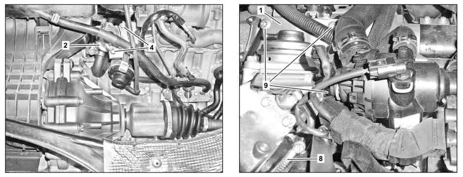
P14.20-2279-08
1 Mixing chamber
2 Exhaust gas recirculation cooler
9 Bolts
4 Bolts
8 Screw clamp

P09.20-2265-06
1 Mixing chamber
2 Exhaust gas recirculation cooler
10 Exhaust gas recirculation coolant return flow line
11 Exhaust gas recirculation feed line coolant line
12 Click clamps
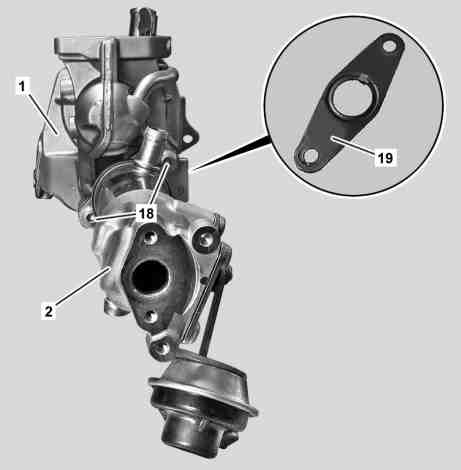
P14.20-2273-12
1 Mixing chamber
2 Exhaust gas recirculation cooler
18 Bolts
19 Gasket
| Remove/install | ||
Danger! | Risk of death caused by vehicle slipping or toppling off of the lifting platform. | Align vehicle between columns of vehicle lift and position four support plates at vehicle lift support points specified by vehicle manufacturer. | |
1 | Raise vehicle with vehicle lift | ||
2 | Lower rear drive module | ||
3 | Drain coolant | ||
4 | Remove bar link | Only loosen left and right upper crossmember on body. | |
5 | Remove exhaust gas recirculation pipe | ||
6 | Remove exhaust gas recirculation switchover valve | For model 451.3## /4## #K up to 452007, remove the ARF switchover valve with bracket. | |
Model 451.3## /4## #K up to 452007 | |||
Model 451.3## /4## #K as of 452008 | |||
7 | Remove air filter housing | ||
8 | Remove bypass switchover valve on exhaust gas recirculation cooler | ||
9 | Remove throttle valve positioner | ||
10 | Remove cable tie (arrows A) | Installation: Replace cable ties (arrows A). | |
11.1 | Remove vacuum hoses (5, 6) and disconnect electrical connector (7) from left boost pressure positioner (Y100) | Model 451.3## /4## #K up to 452007 | |
Installation: Vacuum hoses (5, 6) have different diameters | |||
11.2 | Remove bracket with the LH boost pressure regulator (Y100) | Model 451.3## /4## #K as of 452008 | |
12 | Unscrew bolts (4) from exhaust gas recirculation cooler (2) | ||
13 | Loosen bolt clamp (8) on charge air hose | ||
14 | Unscrew bolts (9) from mixing chamber (1) and pull mixing chamber (1) with exhaust gas recirculation cooler (2) toward front into engine compartment | | |
15 | Mark installation position of exhaust gas recirculation coolant return flow line (10) and exhaust gas recirculation coolant feed line (11) before loosening snap clamps (12) on exhaust gas recirculation cooler (2) | ||
16 | Remove snap clamps (12) from exhaust gas recirculation coolant return flow line (10) and exhaust gas recirculation coolant feed line (11) and remove exhaust gas recirculation coolant return flow line (10) and exhaust gas recirculation coolant feed line (11) from exhaust gas recirculation cooler (2) | Installation: Take note of markings on the AGR coolant return flow line (10) and the AGR coolant line feed line (11). The AGR coolant return flow line (10) and the AGR coolant line feed line (11) can be kinked otherwise during installation. | |
Installation: Replace snap clamps. | |||
Pliers | |||
17 | Remove mixing chamber (1) and exhaust gas recirculation cooler (2) from engine compartment | ||
18 | Unscrew bolts (18) and remove exhaust gas recirculation cooler (2) from mixing chamber (1) | Installation: Replace seal (19) between mixing chamber (1) and exhaust gas recirculation cooler (2). | |
| |||
19 | Install in the reverse order | ||
20 | Test run engine and check exhaust gas for leakage. | ||
21 | Read out fault memory, erase if necessary |
Exhaust gas recirculation
Number | Designation | Engine | |
BA14.20-P-1002-01E | Bolt, exhaust gas recirculation cooler to mixed air housing bottom section | Nm | 10 |
BA14.20-P-1005-01E | Bolt, mixed air housing bottom section to transmission | Nm | 20 |

Pliers
450 589 07 37 00
Powiązane dokumenty
- ad0000p200004mcc
- ar0100p3050mcc
- ar0910p1150mcd
- ar0941p1321mcf
- ar0941p200401mcc
- ar1420p1060mcf
- ar1420p7660mcd
- ar1420p7660mcf
- ar1420p7667mcf
- ar2000p1142mcd
- ar3515p0200mcc
- as0000z001001a Zagrożenie życia na skutek ześlizgnięcia lub spadnięcia pojazdu z podnośnika.