
D05.10-1129-08
Shown on engine 642.9 |
1 | Timing chain | 6 | Camshaft sprocket | 11 | Bearing pin | ||
2 | Slide rail | 7 | Camshaft sprocket | 12 | Bearing pin | ||
3 | Tensioning rail | 8 | Intake camshaft (cylinder head RH) | 13 | Bearing pin | ||
4 | Slide rail | 9 | Exhaust camshaft (cylinder head LH) | 14 | Chain tensioner | ||
5 | Slide rail | 10 | Bearing pin |
Warning | Risk of injury. Moving parts can pinch, crush or, in extreme cases even sever extremities. | No parts of the body or limbs should be within the operating area of mechanical components when moving components. | |
Caution | Risk of injury caused by scraping or cutting body parts on sharp vehicle parts | Always wear protective gloves when working on or near sharp and non-deburred vehicle parts. | |
Caution | Risk of injury to skin and eyes due to handling of engine oil. Risk of poisoning caused by swallowing engine oil | Wear protective gloves, protective clothing and safety glasses. | |
Topical note | Notes on avoiding damage through contamination and foreign objects | ||
| Remove/install | ||
1 | Release camshaft sprocket (7) from intake camshaft (8) and camshaft sprocket (6) from exhaust camshaft (9). | ||
In this connection, piston of cylinder 1 is set to ignition TDC. | |||
Do not remove camshaft sprockets (6, 7). | |||
2 | Remove oil filter housing. | ||
3 | Remove fuel high-pressure pump. | ||
4 | Remove timing case cover. | ||
Crankshaft must not turn during removal of belt pulley. | |||
If crankshaft has turned | |||
| |||
Turn engine to TDC position before removal of timing case cover. | |||
Crank engine at belt pulley of crankshaft | |||
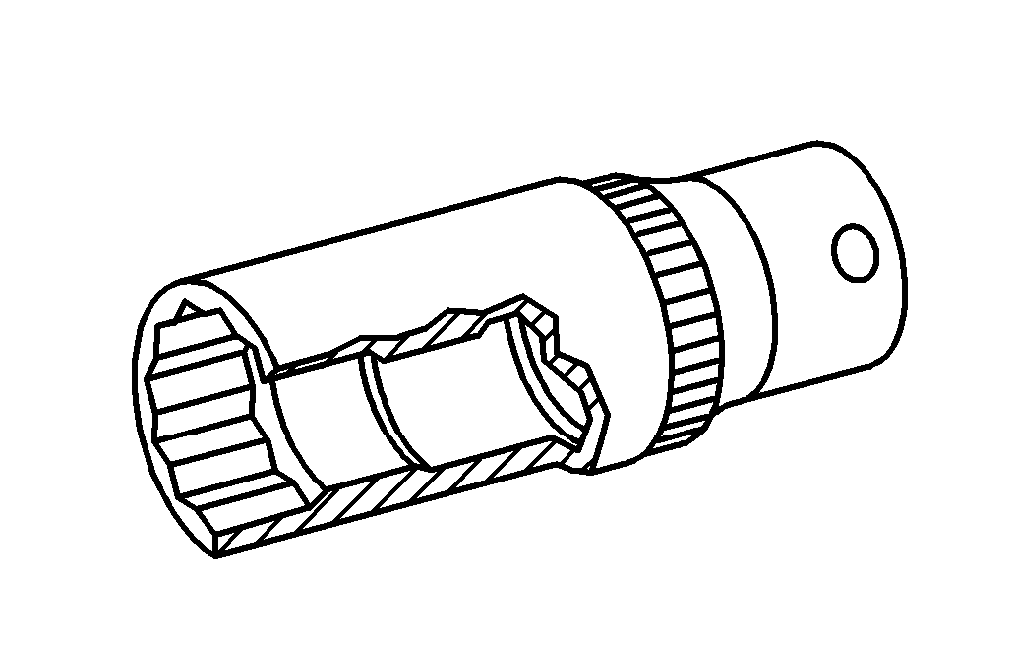
Socket wrench bit | |||
5 | Remove camshaft sprockets (6, 7) and fully remove timing chain (1). | ||
Installation: Check basic position of balance shaft. | |||
6 | Remove slide rail pins from both cylinder heads. | ||
Installation: Screw suitable screws into slide rail pins, drive slide rail pins into cylinder heads and unscrew screws again. | |||
Threaded bolt | |||
Impact extractor | |||
Puller | |||
7 | Remove bearing pin (12) and tensioning rail (3) downwards. | Bearing pin, tensioning rail to crankcase | |
8 | Remove bearing pin (10) and remove slide rail (4). | Bearing pin, slide rail to crankcase | |
9 | Remove bearing pin (11) and slide rail (5) downwards. | Bearing pin, slide rail to crankcase | |
10 | Remove bearing pin (13), press chain tensioner (14) of oil pump chain upwards against spring force and remove slide rail (2) downwards. | Bearing pin, slide rail to crankcase | |
11 | Remove chain tensioner (14) from slide rail (2). | If slide rail (2) is replaced. | |
12 | Install in the reverse order. |


605 589 00 33 00
Puller
116 589 01 34 00
Threaded bolt
116 589 20 33 00
Impact extractor
001 589 65 09 00
Socket wrench bit
Powiązane dokumenty
- ah0000p500001a Wskazówki dotyczące zapobiegania uszkodzeniom na skutek zabrudzeń i ciał obcych
- ar0100d010001tsv
- ar0130d580004tsv
- ar0140d8000tsv
- ar0320d3637tsv
- ar0520d6040tsv
- ar0702d1028tsv
- ar1820d3471tsv
- as0000z000901a Niebezpieczeństwo zakleszczenia lub zmiażdżenia, w skrajnym przypadku obcięcia kończyn podczas prac przy układach mechanicznych.
- as0000z001701a Niebezpieczeństwo obrażeńo elementy pojazdu o ostrych krawędziach.
- as1800z000101a Niebezpieczeństwo obrażeń skóry i oczu podczas kontaktu z olejem silnikowym. Niebezpieczeństwo zatrucia wskutek połknięcia oleju silnikowego