AR01.30-D-5800NB | Remove/install cylinder head | 14.2.12 |
ENGINE 647.981 in MODEL WD1, WD2, WD3, WD6, WD7, XD1, XD2, XD3, XD4, XD5, XD6, XD7, YD1, YD2, YD3, YD4, YD5, YD6, YD7
ENGINE 647.981 in MODEL 903.61 /66 /67, 904.61 /66 with CODE (ZU7) National version for Canada
ENGINE 647.981 in MODEL 903.61 /66 /67, 904.61 /66 with CODE (ZU8) National version for USA
ENGINE 647.981 in MODEL 903.61 /62 /66 /67, 904.61 /62 /66 with CODE (ZU9) National version for Mexico

D01.30-1020-06
1 Cylinder head
2 Charge air distribution pipe
3 Support
4 Fuel hose
5 Fuel pipe
6 Fuel pipe
7 Fuel pipe
8 Charge air hose
9 High pressure pump intermediate gear
10 Bush
11 Screw
12 Turbocharger
13 Oil line
14 Sealing ring
15 Oil dipstick guide tube of automatic transmission
16 Coolant pipe
17 Fitting sleeve
18 Camshaft housing

D01.30-1021-06
1 Cylinder head
8 Charge air hose
12 Turbocharger
13 Oil line
16 Coolant pipe
19 Noise insulation
20 Sealing ring
21 Exhaust clamp
22 Exhaust pipe
23 Exhaust manifold
24 Exhaust gas recirculation positioner
25 Coolant hose
26 Coolant hose
27 Coolant hose
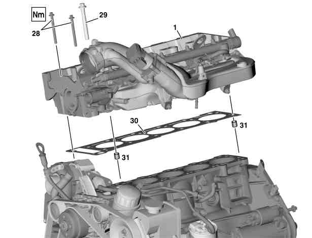
D01.30-1022-06
1 Cylinder head
28 Bolts
29 Cylinder head bolt
30 Cylinder head gasket
31 Fitting sleeve
| Remove/Install | ||
Danger! | Risk of explosion caused by fuel igniting, risk of poisoning caused by inhaling and swallowing fuel as well as risk of injury to eyes and skin caused by contact with fuel. | No fire, sparks, open flames or smoking. Wear protective clothing when handling fuel. | |
Danger! | Risk of explosion caused by oxyhydrogen gas. Risk of poisoning and caustic burns caused by swallowing battery acid. Risk of injury caused by burns to skin and eyes from battery acid or when handling damaged lead-acid batteries | No fire, sparks, open flames or smoking. Wear acid-resistant gloves, clothing and safety glasses. Pour battery acid only into suitable and appropriately marked containers. | |
1 | Disconnect battery ground cable | ||
| Notes on battery | ||
2 | Remove heat shield above turbocharger | ||
3 | Remove cylinder head cover | ||
4 | Drain coolant | Installation: Before filling the cooling system check for leaktightness. | |
5 | Disconnect engine wiring harness at generator and turbocharger (12), guide out to the top along the engine and place to the side | Installation: Ensure correct routing of engine wiring harness. | |
| |||
| |||
6 | Detach fuel lines (6, 7) at the support (3) | ||
7 | Detach brackets of fuel lines (6, 7) at charge air distribution tube (2) | ||
8 | Detach support (3) at charge air distribution tube (2) and only slacken at crankcase | | |
| |||
9 | Detach fuel hose (4) at fuel line (5) | Collect escaping fuel. | |
10 | Remove camshafts | ||
11 | Remove the camshaft housing (18) from cylinder head (1) | Installation: At the time of fitting, pay attention to the fitted sleeves (17) for locating the camshaft housing (18). | |
12 | Remove intermediate gear of high pressure pump (9) | ||
13 | Detach oil feed line (13) at turbocharger (12) and at cylinder head (1) | Replace sealing ring (14). | |
| |||
| |||
14 | Slacken support at turbocharger (12) and at crankcase | Only slacken bolts, in order to mount the turbocharger (12) free of tension. | |
| |||
| |||
15 | Detach noise insulation (19) at the turbocharger (12) | Installation: Install new sealing ring (20). | |
16 | Detach exhaust clamp (21) at turbocharger (12) | ||
17 | Detach the turbocharger (12) at the exhaust manifold (23) | Installation: Replace gasket between turbocharger (12) and exhaust manifold (23). | |
| |||
18 | Detach oil dipstick guide tube for automatic transmission (15) at cylinder head (1) | ||
19 | Detach coolant pipe (16) at cylinder head (1) and place to the side with connected coolant hoses | ||
20 | Detach the charge air hose (8) at the charge air manifold (2) | Pull up clamp at charge air distribution tube (2). | |
21 | Detach the coolant hose (25) at the exhaust gas recirculation positioner (24) | ||
22 | Unplug plug at exhaust gas recirculation positioner (24) | ||
23 | Detach coolant hoses (26, 27) at the coolant thermostat housing | Check condition of coolant hoses (26, 27) and hose clamps, replace if necessary. | |
24 | Unscrew bolts (28), and loosen and unscrew the cylinder head bolts (29) in stages | Slacken cylinder head bolts (29) in the reverse order of the tightening pattern once engine has cooled down. | |
Installation: Observe tightening pattern of bolts (28) and of cylinder head bolts (29). Oil thread and head contact surface of cylinder head bolts (29) and insert. Bolts (28) and cylinder head bolts (29) need not be tightened again. | |||
| |||
| |||
25 | Check cylinder head bolts (29), replace if necessary | ||
26 | Take cylinder (1) off the crankcase | Installation: Fit new cylinder head gasket (30) onto the crankcase and fix with fitted sleeves (31). | |
When fitting on the cylinder head (1) observe fitted sleeves (31) for locating. | |||
27 | Clean cylinder head separating surfaces and tapped holes | Blow out tapped holes free of oil and water. | |
28 | Check cylinder head separating surface | Face-grind cylinder head separating surface if necessary | |
29 | Install in the reverse order | ||
30 | Inspect ATF level of automatic transmission | ||
| Automatic transmission - oil and filter change | ||
Danger! | Risk of accident caused by vehicle starting off by itself when engine is running. Risk of injury caused by contusions and burns when working in engine during starting procedure | Secure vehicle to prevent it from moving. | |
Danger! | Risk of explosion caused by ignition or explosion of fuel. Risk of injury to skin and eyes caused by fuel jets or leakage. | Keep all ignition sources out of hazard area. Do not carry out any work on the system when it is pressurized. | |
31 | Check oil leakage of vehicle and check for leaks in the fuel system | Run engine until warm, switch off and inspect for leaks. | |
32 | Encode radio, set clock |
Cylinder head/cylinder head bolts
Number | Designation | Engine | ||
BE01.30-P-1001-04A | Cylinder head bolt | Thread diameter | M | 12 |
Length (L) when new | mm | 102 | ||
max. length (L) | mm | 104 | ||
For picture, see | ||||
Cylinder head tightening torques
Number | Designation | Engine | ||
BA01.30-P-1001-01I | Bolt of cylinder head to timing case cover | M8 | Nm | 20 |
BA01.30-P-1002-01I | Bolt, cylinder head to crankcaseM12 | 1st stage | Nm | 15 |
2nd stage | Nm | 60 | ||
Step 3 | ° | 90 | ||
4th stage | ° | 90 | ||
Turbocharger
Number | Designation | Engine | ||
BA09.40-P-1001-01C | Flange connection of exhaust manifold to turbocharger | Nm | 30 | |
BA09.40-P-1004-01C | Oil feed line to turbocharger | Screw socket | Nm | 20 |
Banjo bolt | Nm | 18 | ||
BA09.40-P-1005-01C | Bolt of oil feed line to cylinder head | Nm | 9 | |
BA09.40-P-1006-01C | Bolt of support to turbocharger | Nm | 30 | |
BA09.40-P-1007-01C | Bolt of turbocharger support to crankcase | Nm | 20 | |
Charge air pipe/charge air cooling
Number | Designation | Engine 647.981 | |
BA09.41-N-1002-01F | Bolt of support to charge air distribution pipe | Nm | 14 |
BA09.41-N-1003-01F | Bolt of support of charge air distribution pipe to crankcase | Nm | 20 |
Alternator
Powiązane dokumenty
- ah5410p000101a Wskazówki dotyczące akumulatora
- ah5410p000101a
- ap2700d2702c Wymiana oleju i filtra oleju automatycznej skrzyni biegów
- ar0120d5014nb
- ar0130p580001tb Schemat dokręcania śrub głowicy cylindrów
- ar0130p580003hb Sprawdzenie śrub głowicy cylindrów
- ar0510d4650nb
- ar0520d6992nb
- ar2000d1140na
- as0000z000501a Niebezpieczeństwo wypadku na skutek samoczynnego ruszenia przy pracującym silniku. Niebezpieczeństwo obrażeń na skutek zmiażdżenia lub poparzenia przy wykonywaniu czynności podczas rozruchu lub przy pracującym silniku.
- as0716z000101a Niebezpieczeństwo eksplozji w wyniku zapalenia się oparów paliwa. Niebezpieczeństwo obrażeń skóry i oczu przez wytryskujący strumień paliwa.
- as4700z000101a Niebezpieczeństwo wybuchu wskutek zapalenia, niebezpieczeństwo zatrucia wskutek wdychania i połknięcia paliwa oraz niebezpieczeństwo obrażeń wskutek kontaktu skóry i oczu z paliwem.
- as5410z000101a Niebezpieczeństwo pożaru/wybuchu z powodu zwarcia i wydostającego się gazu piorunującego. Niebezpieczeństwo obrażeń z powodu poparzenia oczu, skóry i śluzówki przez elektrolit akumulatora/mgiełkę lub przez zwarcie i działanie