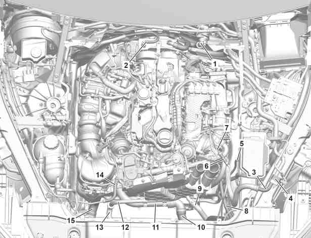
1 | Coolant hose |
2 | Vacuum line |
3 | Refrigerant line |
4 | Separation point |
5 | Vacuum line |
6 | Coolant hose |
7 | Coolant line |
8 | Refrigerant line |
10 | Coolant hose |
11 | Coolant line |
12 | Coolant line |
13 | Coolant hose |
14 | Coolant hose |
15 | Coolant hose |
P01.10-A024-06

Shown on model 167.117/317 |
16 | Electrical connector |
17 | Coolant hose |
P01.10-A227-06

20 | Strut |
21 | Strut |
22 | Ground cable |
23 | Fuel hoses |
24 | Fuel lines |
25 | Bracket |
26 | Heat shield |
27 | Electrical connector |
28 | Electrical wiring harness |
P01.10-A025-06

Shown on model 167.117/317 |
40 | High-voltage plug |
41 | Cable duct |
42 | Electrical connector |
43 | Electrical line |
44 | High-voltage plug |
45 | High-voltage line |
P01.10-A226-06
Danger | Risk of death when working on component parts and systems with U >= 30 V alternating voltage (AC) or U >= 60 V direct voltage (DC) | Do not touch damaged or defective live component parts and lines or non-insulated electrical connections and lines.Engine 654.9 in model 167.117/317 | |
Danger | Risk of explosion caused by fuel igniting, risk of poisoning caused by inhaling and swallowing fuel as well as risk of injury to eyes and skin caused by contactwith fuel. | No fires, sparks, open flames or smoking. Pour fuels into suitable and appropriately marked containers only. | |
Warning | Risk of injury. Moving parts can pinch, crush or, in extreme cases even sever extremities. | No parts of the body or limbs should be within the operating area of mechanical components when moving components. | |
Warning | Risk of injury caused by pinching or crushing when working on springs or spring bodies that are under tension | Use only approved tensioning devices; additionally screen off hazardous area if necessary. Check special tools for damage and proper operation (visual inspection). Wear protective gloves. | |
Warning | Risk of injury. Skin or eye injuries may result when handling hot or glowing objects. | Wear protective gloves, protective clothing and safety glasses, if necessary. | |
Warning | Risk of injury to skin and eyes suffering scalding from contact with hot coolantspray. Risk of poisoning from swallowing coolant. | Do not open cooling system unless coolant temperature is below 90 °C. Open cap slowly and release the pressure. Do not pour coolant into beverage containers. | |
Caution | Risk of injury caused by scraping or cutting body parts on sharp vehicle parts | Always wear protective gloves when working on or near sharp and non-deburred vehicle parts. | |
Topical note | Notes on coolant | ||
Topical note | Protect air conditioning circuit and components from moisture when carrying out repair work | ||
Topical note | General information on vehicles with high-voltage on-board electrical system and/or lithium-ion battery and/or gaseous-fuel drive system as well as personal protective equipment | Engine 654.9 in model 167.117/317 | |
Topical note | Notes on technical cleanliness when working on high-voltage on-board electrical system | Engine 654.9 in model 167.117/317 | |
Topical note | Information on preventing damage to electronic components due to electrostatic discharge | ||
Topical note | Procedure for a damaged or leaky air conditioning system | ||
Topical note | Notes on avoiding damage through contamination and foreign objects | ||
Topical note | Notes on bolted connections with self tapping screws | ||
Topical note | Notes on self-locking nuts and bolts | ||
Topical note | Notes on air suspension | ||
Notes on handling refrigerant R1234yf | |||
Notes on safety-relevant components | Engine 654.9 in model 167.117/317 | ||
Notes on automatic transmission | Engine 654.9 in model 167 with transmission 725.0 | ||
Notes about Common-Rail components | |||
Use of engine no. when installing reconditioned engines and factory-new replacement engines or crankcases | |||
| Remove/install | ||
1 | Secure vehicle on vehicle lift. | ||
2 | Pump pneumatic pressure of suspension struts using vehicle diagnosis system to central reservoir. | Engine 654.9 in model 167 | |
| |||
| |||
Select menu item "Actuations" in active suspension and damping system control unit. | |||
Installation: Pump pneumatic pressure using vehicle diagnosis system from central reservoir to suspension struts. | |||
3 | Put transmission into neutral position. | ||
4 | Release parking brake. | ||
5 | Move front wheels to straight-ahead position and fix steering wheel in place with holding device. | | |
Retainer device | |||
6 | Remove voltage of high-voltage on-board electrical system. | Engine 654.9 in model 167.117/317 | |
7 | Disconnect the ground line for the on-board electrical system battery(G1). | ||
8 | Remove lower engine compartment paneling. | ||
Installation: Only install lower engine compartment paneling after leak test. | |||
9 | Remove underfloor panels. | ||
Installation: Install underfloor paneling only after the leak test. | |||
10 | Drain off coolant. | ||
11 | Drain engine oil. | If necessary. | |
| |||
12 | Discharge air conditioning system. | ||
13 | Remove service flaps from engine compartment. | ||
Nut to wiper arm on front windshield wiper system | |||
14 | Remove air filter housing. | ||
15 | Remove engine air intake duct downstream of air filter. | ||
Installation: Do not install engine cover until after leak test. | |||
16 | Remove coolant hose (1) from the firewall and seal openings with protective covers. | ||
Set of protective covers | |||
17 | Remove vacuum line (2) from vacuum line. | ||
18 | Remove impact plate. | ||
19 | Disconnect engine wiring harness. | ||
Nut, positive line to engine compartment/vehicle interior prefuse box | |||
20 | Remove refrigerant line (3) from connecting point (4), seal connections with suitable stop plugs and protective covers. | ||
| Compressor oils (specification 362.1) | ||
Installation: Replace sealing ring and moisten with compressor oil. | |||
Nut, refrigerant line connecting point | |||
Set of protective caps | |||
Assembly tool | |||
Record plug | |||
21 | Fasten refrigerant line (3) to engine. | ||
22.1 | Remove refrigerant line (8) from refrigerant compressor with magnetic clutch (A9/7). | Engine 654.9 in model 167 (except 167.117/317) | |
22.2 | Remove electrical connector (16), high-voltage plug (44), and refrigerant line (8) from electric refrigerant compressor (A9/5). | Engine 654.9 in model 167.117/317 | |
Remove/install electric refrigerant compressor | |||
Detach/attach high-voltage plug | |||
Bolt, high-voltage plug to DC charger/high-voltage battery | |||
Bolt, high-voltage connector to high-voltage power distributor | |||
23 | Remove vacuum line (5) and attach it to the engine. | ||
24 | Remove coolant hose (6) from coolant line(7) and seal connections with suitable stop plugs. | Hose clamp pliers | |
Record plug | |||
25 | Remove coolant hose (14) from coolant line and seal connections with suitable stop plugs. | Hose clamp pliers | |
Record plug | |||
26 | Remove coolant hose (15) from the thermostat housing and seal openings with protective covers. | ||
Set of protective covers | |||
27 | Remove the oil cooler from fan unit and attach it to the engine. | Engine 654.9 in model 167 with transmission 725.0 | |
28 | Remove coolant hose (10) from coolant line(11) and seal openings with protective covers. | ||
Set of protective caps | |||
Set of protective covers | |||
29 | Remove coolant hose (13) from coolant line(12) and seal openings with protective covers. | ||
Set of protective caps | |||
Set of protective covers | |||
30 | Remove coolant hose (17) from coolant line (12), seal with protective covers, and attach to vehicle. | Engine 654.9 in model 167.117/317 | |
Set of protective caps | |||
Set of protective covers | |||
31 | Release and disconnect electrical connector from DPF differential pressure sensor (B28/8), remove DPF differential pressure sensor (B28/8) with molded hoses attached, and attach to engine. | ||
32 | Remove AdBlue® metering valve (Y129) from catalytic converter. | ||
33 | Release and disconnect electrical connector of left switchable engine mount (Y123) and right switchable engine mount (Y123/1). | ||
34 | Release and disconnect electrical connectors from power steering actuator motor. | ||
35 | Release and disconnect electrical connector at sound generator (H4/16) and at electric vacuum pump (M56), expose wiring harness and attach to vehicle. | Engine 654.9 in model 167.117/317 | |
36 | Expose the wiring harness of the electrical power steering and attach it to the vehicle. | ||
37 | Remove fuel hoses (23) from fuel lines(24) and collect escaping fuel using suitable container. | Installation: Install new fuel hoses (23). | |
Pliers for click clamps | |||
38 | Open holder (25), remove fuel hoses (23), and seal connections with suitable stop plugs. | Record plug | |
39 | Remove the ground line (22) from the transmission. | Engine 654.9 in model 167 with transmission 725.0Bolt, ground line to transmission housing | |
40 | Remove exhaust system. | ||
Reinstall rear engine carrier and screw in screws. | |||
41 | Detach drive shaft from transmission. | ||
42 | Release propeller shaft of the front axle differential from the transfer case. | Engine 654.9 in model 167 with transmission 725.0 | |
43 | Release and disconnect the electrical connector from the transfer case, and expose the electrical line. | Engine 654.9 in model 167 with transmission 725.0 | |
44 | Remove heat shield(26). | Engine 654.9 in model 167 with transmission 725.0Screw/bolt, heat shield to oil pan | |
45 | Release and disconnect electrical connector(27) and expose electric line. | ||
46 | Release and disconnect the electrical connector from the transmission, and expose the electrical wiring harness(28). | ||
47 | Remove steering coupling from steering shaft. | ||
48 | Remove front wheel and tire assemblies. | ||
49 | Remove left and right fender liners. | ||
50 | Remove rotational speed sensors from steering knuckles. | ||
51 | Expose electric lines of spring links and steering knuckles. | ||
52 | Remove brake calipers with the brake caliper supports and fasten to the vehicle free of tension. | Engine 654.9 in model 167 | |
Engine 654.9 in model 167 | |||
53 | Remove steering knuckles from upper transverse control arms. | ||
| |||
54 | Remove suspension struts from bottom lower control arms. |
| |
55 | Support front axle carrier with lifting platform. | ||
| 000 588 03 62 00 Lifting platform | ||
56 | Secure engine transmission unit against slipping and falling down with tensioning strap. | ||
| 000 588 03 62 00 Lifting platform | ||
57 | Remove rear engine carrier from frame floor assembly. | ||
The rear engine support remains on the transmission. | |||
58 | Remove struts (20, 21). | ||
59.1 | Lower engine transmission unit with front axle carrier. | Engine 654.9 in model 167 (except 167.117/317) | |
| 000 588 03 62 00 Lifting platform | ||
| |||
Aid of helper required. | |||
59.2 | Lower engine transmission unit with front axle carrier until high-voltage plug (40) is accessible. | Engine 654.9 in model 167.117/317 | |
| 000 588 03 62 00 Lifting platform | ||
| |||
Aid of helper required. | |||
60 | Release and disconnect electrical connector (42), seal openings with protective covers, and expose electric line (43). | Engine 654.9 in model 167.117/317 | |
Set of protective caps | |||
61 | Release and disconnect high-voltage plug (40), seal connections with protective covers, and expose cable duct (41). | Engine 654.9 in model 167.117/317 | |
| |||
Bolt, high-voltage plug to DC charger/high-voltage battery | |||
Bolt, high-voltage connector to high-voltage power distributor | |||
Set of protective covers | |||
62 | Expose high-voltage line (45). | Engine 654.9 in model 167.117/317 | |
| |||
63 | Carefully lower engine transmission unit with the front axle carrier. | Engine 654.9 in model 167.117/317 | |
| 000 588 03 62 00 Lifting platform | ||
| |||
Aid of helper required. | |||
64 | Fasten steering knuckles with a tensioning strap to the engine. | ||
65 | Install in the reverse order. | ||
Concluding tasks | |||
66 | Perform chassis alignment. | ||
67 | Read out and delete fault memory. | ||
| |||
68 | Calibrate Distance Pilot DISTRONIC controller unit. | Engine 654.9 in model 167 | |
| |||
69 | Check engine oil level and correct if necessary. | ||
| |||
Warning | Risk of accident from vehicle starting off by itself when engine running. Risk of injury (bruises and burns) resulting from working on the engine while it is being started or when it is running. | Secure vehicle to prevent it from starting off by itself. Wear closed and snug-fitting work clothes. Do not touch hot or rotating parts. | |
Warning | Risk of burn injuries, suffocation and poisoning when working on the exhaust system and the components connected to it. Risk of suffocation and risk of poisoning caused by inhalation of gaseous and solid components of the exhaust. Risk of poisoning caused by skin contact with solid components of the exhaust. | Wear protective clothing and safety glasses. Use the extraction system. Move people out of the hazard area. | |
70 | Perform engine test run. While doing so, check engine for proper operation and leak tightness. |


001 589 03 91 00
Set of protective covers
001 589 00 91 00
Set of protective caps
171 589 00 37 00
Pliers for click clamps
129 589 01 21 00
Retainer device


000 589 93 63 00
Assembly tool
454 589 00 37 00
Hose clamp pliers
129 589 00 91 00
Record plug
001 589 01 91 00
Set of protective covers

001 589 02 91 00
Set of protective caps
Powiązane dokumenty
- ad0000p200006me
- ah0000n000101a Wskazówki dotyczące samozabezpieczających śrub i nakrętek
- ah0000p000701sf Wskazówki dotyczące połączeń śrubowych z samonacinającymi śrubami
- ah0000p500001a Wskazówki dotyczące zapobiegania uszkodzeniom na skutek zabrudzeń i ciał obcych
- ah0000z001901a Wskazówki dotyczące elementów wpływających na bezpieczeństwo
- ah0000z030001a Ogólne wskazówki dotyczące pojazdów z instalacją wysokiego napięcia i/lub akumulatorem litowo-jonowym i/lub gazowym systemem napędu oraz osobistego wyposażenia ochronnego
- ah0110p000101a Obchodzenie się z numerem silnika podczas montażu silników zamiennych i fabrycznie nowych silników zastępczych lub skrzynia korbowej z obudową cylindrów
- ah0716p000201tx Wskazówki dotyczące zespołów układu Common-Rail
- ah2000n208001a Wskazówki dotyczące płynu chłodzącego
- ah2719p000101nkb Wskazówki dotyczące automatycznej skrzyni biegów
- ah2719p000101nkb
- ah3222p100001t Wskazówki dotyczące zawieszenia pneumatycznego
- ah5400p000101a Wskazówki dotyczące zapobiegania uszkodzeniom elementów elektronicznych na skutek rozładowania potencjału elektrostatycznego
- ah5400p000401rfw Wskazówki dotyczące technicznej czystości podczas prac przy instalacji wysokiego napięcia
- ah8330n000401a Postępowanie przy uszkodzonym lub nieszczelnym układzie klimatyzacji
- ah8330n000501a Ochrona obwodu i elementów układu klimatyzacji przed wilgocią podczas napraw
- ah8330p000302a Wskazówki dotyczące obchodzenia się z czynnikiem chłodzącym R1234yf
- ap1800p0101fm Wymiana oleju silnikowego i filtra oleju
- ap1800p1812ski Kontrola poziomu oleju silnikowego poprzez zestaw wskaźników
- ar0060p1006a Podnoszenie, opuszczenie pojazdu na podnośniku
- ar0110p240502oid
- ar0704p0025olm
- ar0910p1150olm
- ar0910p8130olm Demontaż i montaż kanału ssania powietrza silnika za filtrem powietrza
- ar1322p1202olm
- ar1518p100005olm
- ar2000p1142olm
- ar2020p744101rq Otwieranie i zamykanie złącza przewodu płynu chłodzącego
- ar2210p4330olm
- ar2210p4360oid
- ar2755p1000oid
- ar2810p0100oid
- ar3225p1017me
- ar3225p1017meh
- ar3310p0100me
- ar3310p0100mex
- ar3325p0400me
- ar4010p1102me
- ar4020p0200me
- ar4110p0050oid
- ar4110p0070oid
- ar4210p0070me
- ar4210p0070mex
- ar4230p0713me
- ar4610p8000me
- ar4770p000501meh Odłączanie i podłączanie wtyku wysokiego napięcia
- ar4770p1000meh Wyłączanie/uruchamianie instalacji wysokiego napięcia
- ar4910p7142oid
- ar4920p2000olm
- ar5410p0003me
- ar5410p0003me
- ar6120p1105me
- ar6130p1001me
- ar8330p1760me
- ar8330p1760me
- ar8355p5310olm
- ar8355p5311olr
- ar8810p1301me
- as0000z000101a Niebezpieczeństwo obrażeń na skutek zakleszczenia lub zmiażdżenia podczas czynności przy wstępnie naprężonych resorach lub elementach sprężynujących.
- as0000z000201a Niebezpieczeństwo zranienia skóry i oczy na skutek kontaktu z gorącymi lub żarzącymi się przedmiotami
- as0000z000501a Niebezpieczeństwo wypadku na skutek samoczynnego ruszenia przy pracującym silniku. Niebezpieczeństwo obrażeń na skutek zmiażdżenia lub poparzenia przy wykonywaniu czynności podczas rozruchu lub przy pracującym silniku.
- as0000z000901a Niebezpieczeństwo zakleszczenia lub zmiażdżenia, w skrajnym przypadku obcięcia kończyn podczas prac przy układach mechanicznych.
- as0000z001701a Niebezpieczeństwo obrażeńo elementy pojazdu o ostrych krawędziach.
- as0000z003501a Zagrożenie życia podczas prac przy elementach i systemach U >=30 V napięcie zmienne (AC) bądź U >=60 V napięcie zmienne
- as2000z000101a Niebezpieczeństwo zranienia skóry i oczu przez poparzenie wytryskującym, gorącympłynem chłodzącym. Niebezpieczeństwo zatrucia na skutek połknięcia płynu chłodzącego
- as4700z000101a Niebezpieczeństwo wybuchu wskutek zapalenia, niebezpieczeństwo zatrucia wskutek wdychania i połknięcia paliwa oraz niebezpieczeństwo obrażeń wskutek kontaktu skóry i oczu z paliwem.
- as4900z000101a Niebezpieczeństwo poparzenia, uduszenia i zatrucia podczas prac przy układzie wydechowym i połączonych z nim elementach. Niebezpieczeństwo uduszenia i zatrucia przez wdychanie gazowych i stałych składników spalin. Niebezpieczeństw
- bb0040p036201a
- ws0100p0091a