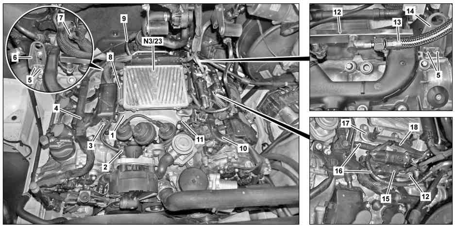
D09.20-1023-09
1 Resonance intake manifold
2 Electrical connector
3 Service valve
4 Right feed line duct
5 Bolts
6 Right lifting eye
7 Electrical connector
15 Electrical connector
16 Hoses
17 Left control unit bracket
18 Electrical line
N3/23 ME-SFI [ME] control unit
8 Right control unit bracket
9 Vacuum line
10 Left feed line duct
11 Electrical connector
12 Fuel distributor
13 Fuel pipe
14 Left lifting eye

D09.20-1024-09
1 Resonance intake manifold
12 Fuel distributor
17 Left control unit bracket
19 Vacuum hoses
20 Gasket
21 Bolts
Y62/3 Cylinder
3 fuel injection valve
Y62/4 Cylinder
4 fuel injection valve
Y62/5 Cylinder
5 fuel injection valve
Y62/6 Cylinder
6 fuel injection valve
B28/9 Left intake manifold swirl flap position sensor
B28/10 Right intake manifold swirl flap position sensor
M16/5 Throttle valve positioner
Y62/1 Cylinder
1 fuel injection valve
Y62/2 Cylinder
2 fuel injection valve
| Remove/install | ||
Danger! | Risk of explosion caused by fuel igniting, risk of poisoning caused by inhaling and swallowing fuel and risk of injury to eyes and skin caused by contact with fuel | No fire, sparks, open flames or smoking. Wear protective clothing when handling fuel. | |
1 | Remove ME-SFI control unit (N3/23) | ||
2 | Remove air duct housing | ||
3 | Disconnect vacuum line (9) on resonance intake manifold (1) | ||
4 | Disconnect electrical connector on throttle valve positioner (M16/5) | ||
5 | Disconnect electrical connector (11) | ||
6 | Remove electrical line (18) on left control unit holder (17) | Installation: Install new cable ties. | |
7 | Disconnect electrical connector (15) f and remove on fuel distributor (12) | ||
8 | Disconnect hoses (16) for crankcase ventilation system | Detach hoses (16) on Y-fitting. | |
9 | Disconnect electrical connector (2) | ||
10 | Disconnect electrical connector (7) | ||
11 | Remove right control unit holder (8) | | |
12 | Remove bolts (5) on right lifting eye (6) and left lifting eye (14) | | |
13 | Remove right feed line duct (4) and left feed line duct (10) | | |
| |||
14 | Remove rear feed line duct on resonance intake manifold (1) | | |
15 | Disconnect electrical connector on left position sensor intake manifold swirl flap (B28/9) and right position sensor intake manifold swirl flap (B28/10) | ||
16 | Remove electrical connectors at fuel injection valves (Y62/1, Y62/2, Y62/3, Y62/4, Y62/5, Y62/6) | ||
17 | Reduce fuel pressure with the pressure hose via the service valve (3) | ||
| |||
| |||
18 | Remove fuel line (13) on fuel distributor (12) and seal connections with a suitable stop plug | Catch escaping fuel with an absorbent rag. | |
| |||
19 | Remove bolts (21) | | |
20 | Lift resonance intake manifold (1) to the front and detach vacuum hoses (19) from connection fittings on resonance intake manifold (1) | Detach vacuum hoses (19) carefully; the connection fittings on the resonance intake manifold (1) can break. | |
Installation: Check vacuum hoses (19) for damage; replace if necessary. | |||
21 | Remove resonance intake manifold (1) and close off openings for intake tract of cylinder head using rags | Installation: Clean sealing surfaces. Clip new seals (20) onto resonance intake manifold (1). | |
22 | Remove left control unit holder (17) on resonance intake manifold (1) | When replacing resonance intake manifold (1). | |
| |||
23 | Remove fuel distributor (12) with fuel injection valves (Y62/1, Y62/2, Y62/3, Y62/4, Y62/5, Y62/6) on resonance intake manifold (1) | When replacing resonance intake manifold (1). | |
Installation: Replace O rings on fuel injection valves (Y62/1, Y62/2, Y62/3, Y62/4, Y62/5, Y62/6). | |||
| |||
24 | Detach throttle valve actuator (M16/5) on resonance intake manifold (1) | When replacing resonance intake manifold (1). | |
Installation: Replace seal on brake booster (M16/5) | |||
| |||
25 | Remove left intake manifold swirl flap position sensor (B28/9) and right intake manifold swirl flap position sensor (B28/10) on resonance intake manifold (1) | When replacing resonance intake manifold (1). | |
| |||
26 | Install in the reverse order | ||
Danger! | Risk of accident caused by vehicle starting off by itself when engine is running. Risk of injury caused by contusions and burns during starting procedure or when working near the engine as it is running | Secure vehicle to prevent it from moving by itself. | |
27 | Test run engine and check engine for leaks around resonance intake manifold (1) |
Cylinder head
Number | Designation | Engine | |||
BA01.30-N-1004-01R | Bolt connecting suspension lug to cylinder head | M8 | Nm | 18 | |
Injection nozzles, injection valves, lines
Number | Designation | Engine | ||
BA07.03-N-1001-01G | Union nut, fuel feed line to fuel distributor | Nm | 24 | |
BA07.03-N-1002-01G | Bolt connecting fuel distributor to resonance intake manifold | Nm | 14 | |
BA07.03-N-1003-01G | Protective cap to service valve | Nm | 15 | |
Control unit
Number | Designation | Engine | ||
BA07.08-N-1002-01A | Bolt, control unit holder to resonance intake manifold | Nm | 10 | |
ME-SFI [ME] injection and ignition system
Number | Designation | Engine | ||
BA07.61-N-1001-01A | Bolt, throttle valve actuator to resonance intake manifold | Nm | 10 | |
Intake manifold
Number | Designation | Engine | ||
BA09.20-N-1001-01B | Bolt connecting resonance intake manifold to cylinder head | Nm | 9 | |
BA09.20-N-1002-01B | Bolt, intake manifold swirl flap position sensor to resonance intake manifold | Nm | 6 | |
Engine wiring harness
Number | Designation | Engine | ||
BA15.18-N-1001-01D | Bolt, feed line duct to resonance intake manifold | Nm | 8 | |
BA15.18-N-1002-01D | Bolt, feed line duct to cylinder head cover | Nm | 8 | |

Pressure hose
119 589 04 63 00
참조 문서
- ar0703d146001us
- ar0708d7008us
- ar0920d0080us
- as0000z000501a 엔진이 작동 중인 상태에서 급발진에 의한 사고 위험 시동 또는 구동 중인 엔진 근처에서 작업할 때 차량에 부딪히거나 열에 의한 상해 위험
- as4700z000101a 인화에 의한 폭발 위험, 연료의 흡입 및 음용에 의한 중독 위험, 연료의 피부 및 안구 접촉에 의한 상해 위험