Function requirements for charging - general
Circuit 87 M (engine management ON)
Engine runs
The circuit relay 87M(F58kN) is switched on for circuit 15 ON.
Forced induction, general
The cylinder charging efficiency is improved as a result of forced induction. As a result, the engine torque and power output are boosted. The fuel quantity corresponding to the increased air mass is metered by the ME-SFI control unit (N3/10).
With forced induction, the flow energy of the exhaust gases is used to drive the ATL. The ATLs draw in fresh air via the air filters at the compressor inlets and lead it via the compressor outlets in the charge air pipes upstream to the charge air coolers.
Due to the high rotational speed of the compressor impellers and the resulting high volumetric flow rate, the intake air becomes compressed in the charge air pipes. The compressed charge air flows via the charge air pipes to the charge air coolers. These subsequently cool the air which was heated by the compression and lead it via the charge air distributor to the cylinders.

Design of charging system |
1 | Left air filter housing |
2 | Right air filter housing |
110/1 | Left charge air cooler |
110/2 | Right charge air cooler |
121/1 | Left turbocharger |
121/2 | Right turbocharger |
B17/14 | Left charge air temperature sensor |
B17/15 | Right charge air temperature sensor |
B28/4 | Pressure sensor downstream air filter, left cylinder bank |
B28/5 | Pressure sensor downstream of air filter, right cylinder bank |
B28/20 | Left pressure sensor upstream of throttle valve |
B28/21 | Right pressure sensor upstream of throttle valve |
B28/22 | Left pressure sensor downstream of throttle valve |
B28/23 | Right pressure sensor downstream of throttle valve |
M16/60 | Left throttle valve actuator |
M16/61 | Right throttle valve actuator |
Y101/1 | Left bypass air switchover valve |
Y101/2 | Right bypass air switchover valve |
E | Exhaust gases |
F | Intake air |
G | Charge air uncooled |
H | Charge air cooled |
P09.00-2149-76
Forced induction function sequence
The function sequence for the charging encompasses the following subfunctions:
Function sequence for boost pressure control
Function sequence for bypass air
Function sequence for charge air cooling
Function sequence for boost pressure control
The boost pressure control occurs electropneumatically over the boost pressure control pressure transducer (Y77/1). The vacuum is generated by the mechanical vacuum pump attached to the engine. The pressure transducer boost pressure control is actuated on a characteristics map and load-dependent basis by the ME-SFI control unit for boost pressure control. To do this the ME-SFI control unit evaluates the following sensor signals and functions of the engine management:
Charge air temperature sensor on the left and right, charge air temperature
Pressure sensor upstream of throttle valve on the left and right, boost pressure
Pressure sensor downstream of throttle valve on the left and right, engine load
Pressure sensor downstream of air filter, left and right cylinder bank, intake air pressure
Accelerator pedal sensor (B37), load request made by driver
Crankshaft Hall sensor (B70), engine rpm
Knock sensor system
Transmission overload protection
Overheating protection
In wide open throttle operation, maximum boost pressure builds up.
To reduce the boost pressure, the exhaust flows that drive the ATL are each redirected through bypasses by opening the boost pressure control flaps. To do this the boost pressure control pressure transducer actuates the boost pressure control flap vacuum cell with vacuum from the vacuum pump. The boost pressure control flap vacuum cells react by closing the boost pressure control flap linkages over a rod, which close the bypasses.
If there is no vacuum at the boost pressure control flap vacuum cells, the boost pressure control flaps and thus also the bypasses are opened. The boost pressure control flaps allow the exhaust flow to bypass the turbine wheels (bypass), thus controlling the boost pressure and limiting the turbine speed. In this way the boost pressure can be adapted to the current load demand on the engine.
If there is leakage in the line between the vacuum pump and the vacuum cells then no build up of boost pressure is possible.
To monitor the current boost pressure, the pressure sensors upstream of the left and right throttle valve send the corresponding voltage signal to the ME-SFI control unit. The pressure sensors downstream of the air filter serve to allow the ME-SFI control unit to monitor the charging. The ME-SFI control unit determines the current engine load based on signals from pressure sensors downstream of throttle valve.
The charge air temperature is detected in the charge air cooler by the left and right charge air temperature sensors and sent to the ME-SFI control unit in the form of a voltage signal.
The boost pressure control function can only be assessed if the "boost pressure control adapted" message is displayed with the Xentry Diagnostics. If the ME-SFI control unit or one of the ATLs is replaced, a longer driving distance is required in certain operating conditions, in order to allow the ME-SFI control unit to perform the adaptation. If the hose lines are leaky between the vacuum cells, boost pressure control pressure transducer and charge air cooler, a "boost pressure too high" fault is stored in the ME-SFI control unit. Quick load requirements below the basic charge pressure are controlled via the throttle valve actuator.
Function sequence for bypass air
The ATLs continue turning for a period of time after the start of deceleration mode due to the inertia of the shaft, compressor and turbine wheel.
Through rapid closing of the throttle valve back pressures and unfavorable vibrations occur in the air column downstream of the ATLs. This vibrations would create a condition with a low delivery volume and high pressure conditions at the compressor impellers, which causes charger pumping (brief howling and mechanical stress).
M16If the ME-SFI control unit detects closing of the throttle valves and therefore the decel mode over the left actual value potentiometer 1 (/60r1), right actual value potentiometer 1 (M16/60r2), left actual value potentiometer 2 (M16/61r1) and right actual value potentiometer 2 (M16/61r2), then the left and right switchover valves for bypass air are actuated.
These are located on the charge air coolers and each open a bypass from the charge pressure side downstream of the ATL to the suction side downstream of the air filters. The excess boost pressure and the respective air volumes are rapidly reduced in this way and thus prevent braking of the compressor impeller on the ATL.
If the engine changes from deceleration mode to load operation, the bypass air switchover valve is no longer actuated.
Function sequence for charge air cooling
The charge air cooling maintains a charge air temperature of < 60°C at 20°C ambient temperature. The cooled air downstream of the charge air coolers has a higher density. This increases the cylinder charge, and therefore engine performance.
The tendency to knock and formation of nitrogen oxides (NOx) are also reduced due to lower exhaust temperatures. Both cylinder banks are fitted with a common coolant-cooled charge air cooler. The charge air cooler is attached to the low-temperature circuit with the low-temperature cooler, the wheel arch low-temperature cooler and the low-temperature circuit circulation pump 1 (M43/6) and the low-temperature circuit circulation pump 2 (M43/7).
If the charge air temperature is > 35 °C, the ME-SFI control unit transmits the request to switch on the low-temperature circuit circulation pumps 1 and 2 via the drive CAN (CAN C) to the powertrain control unit (N127). The powertrain control unit actuates the low-temperature circuit circulation pump 1 and 2 via drivetrain LIN (LIN C3).
The ME-SFI control unit detects the current charge air temperature in the charge air coolers over the left and right charge air temperature sensors (voltage signal).

View of low-temperature circuit from the right |
10 | Transmission oil heat exchanger |
14 | Low-pressure cooler |
15 | Expansion reservoir |
110/1 | Left charge air cooler |
110/2 | Right charge air cooler |
M43/6 | Low temperature circuit circulation pump 1 |
M43/7 | Low-temperature circuit circulation pump 2 |
A | Coolant feed |
B | Coolant return flow |
C | Differential/feed low temperature coolant circuit |
P09.41-2837-76
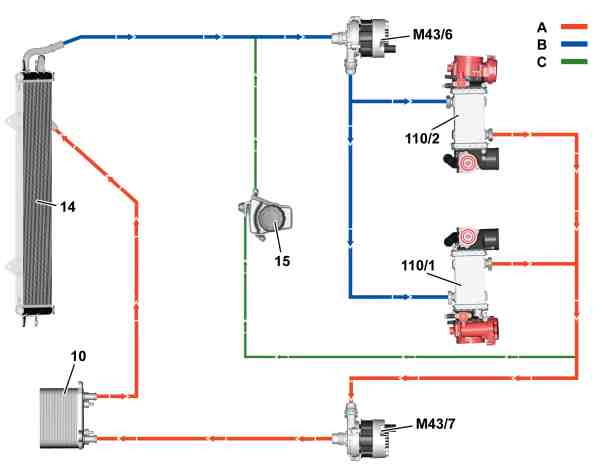
Low-temperature circuit, shown schematically |
10 | Transmission oil heat exchanger |
14 | Low-pressure cooler |
15 | Expansion reservoir |
110/1 | Left charge air cooler |
110/2 | Right charge air cooler |
M43/6 | Low temperature circuit circulation pump 1 |
M43/7 | Low-temperature circuit circulation pump 2 |
A | Coolant feed |
B | Coolant return flow |
C | Differential/feed low temperature coolant circuit |
P20.00-2561-76
Referenced documents
- gf0770p9998mnf Overview of system components for gasoline injection and ignition system with direct injection