
P77.30-2492-09
Shown on left side of vehicle
1 Soft top
1.1 Soft top frame
2 Electrical connector
3 Bolts
4 Connecting panel
10 Seat belt guide
A10 Seat belt extender on left
A11 Right belt extender
A104/1 AM amplifier
5 Screw
6 Nut
7 Foam material
8 Sidebag unit
9 Nut

P77.30-2493-06
Shown on left side of vehicle
1 Soft top
1.1 Soft top frame
12 Screw
13 Bracket
14 Seat belt guide bracket
15 Screw
16 Sealing rail
17 Waistline trim strip
18 Adhesive tape
19 Pin

P77.30-2494-09
1 Soft top
1.2 Soft top support
20 Rear window heater ground line
21 Electrical connector
22 Soft top limit switch electrical line
28 Screw
29 Expansion nut
30 Tolerance compensation element
W29/3 Left C-pillar ground point
23 Screw
24 Expansion nut
25 Tolerance compensation element
26 Electrical connector
27 Rear window heater electrical line

P77.30-2502-07
Shown on left side of vehicle
31 Screw
33 Inner panel
32 Nut

P77.30-2496-06
Shown on left side of vehicle
1 Soft top
1.2 Soft top support
34 Screw
35 Soft top actuation hydraulic cylinder
36 Soft top bow hydraulic cylinder
37 Electrical connector
38 Bolts
39 Cable
40 Antenna electrical line
41 Electrical connector
A104/2 AM amplifier with selection switch
S84/15 Soft top bow "down/up" limit switch

P77.30-2497-09
42 Hydraulic line set
A7/5 Soft top control hydraulic unit
43 Connection plate
| Remove/install | ||
Danger! | Risk of injury caused by moving parts that can pinch, crush or, in extreme cases, even sever extremities | No parts of the body or limbs should be within the operating range of the mechanism when moving components. | |
Danger! | Risk of injury to skin or eyes caused by hydraulic fluid spraying out under high pressure. Risk of poisoning caused by swallowing hydraulic fluid | Depressurize the hydraulic system completely before starting any work on the system. Wear protective clothing and safety glasses. | |
Danger! | Risk of injury caused by scraping or cutting body parts on sharp vehicle parts | Always wear protective gloves when working on or near sharp and non-deburred vehicle parts. Deburr repair panels. | |
Perform assembly work analogously on left and right side of vehicle. | |||
1 | Cover vehicle in rear area | To prevent scratching the paint during assembly work. | |
2 | Remove side paneling in trunk | ||
3 | Connect variable soft top compartment limit switch to wiring harness on vehicle side. | Connect and actuate soft top compartment limit switch on vehicle side so that the soft top (1) can be moved electrically. | |
Remove/install soft top hydraulic pump | |||
4 | Remove lower side paneling in rear | ||
5 | Lower soft top (1) toward front | Leave soft top bow and soft top compartment cover in upright position | |
6 | Disconnect electrical connector (2) from AM amplifier (A104/1) | ||
7 | Remove sidebag (8) | Only on vehicles with code (293) right and left rear sidebag. | |
8 | Remove foam material (7) | ||
9 | Unclip belt guide (10) | ||
10 | Remove bolts (3) | ||
11 | Remove connecting panel (4) | ||
12 | Remove bolt (5) | ||
13 | Unscrew nut (6) | ||
14 | Loosen left belt extender (A10) and right belt extender (A11) and lay down to side with electrical line connected | Installation: Do not twist seat belt. | |
15 | Unscrew bolt (12) from bracket (13) | ||
16 | Remove bracket (13) | Installation: Ensure that bracket (13) is seated correctly in lug (arrow A). | |
17 | Unscrew bolt (15) and lay belt guide bracket (14) down to side | Installation: Do not twist seat belt. | |
| |||
18 | Remove trim strip beltline (17) from side wall paneling starting at front | Mounting wedge | |
19 | Remove shaped part of sealing rail (16) with retaining clamp and adhesive tape (18) from | Installation: Clean bonding area on adhesive tape (18) on B-pillar. Observe flash-off time for cleaner of at least 60 s.
| |
Roller | |||
Cleaner | |||
20 | Pull pin (19) on shaped part on sealing frame (16) out of B-pillar | Installation: Moisten pin (19) on shaped part with lubricant and press into B-pillar. | |
Antifriction agent | |||
21 | Remove sealing rail (16) from side wall inner section | Mounting wedge | |
Installation: Prepare sealing rail (16) for installation: | |||
Prepare sealing profile on roof frame for installation | |||
Allow primer to flash off for at least 90 s, apply primer only once and do not touch with bare fingers, otherwise the adhesive force of the new adhesive strip (18) is not ensured. Attach new adhesive tape (18) to shaped part within one hour, otherwise the adhesive force of the new adhesive tape (18) on shaped part is not ensured. | |||
Adhesive tape | |||
4298 UV primer | |||
Cleaner | |||
Hot air blower | |||
22 | Remove rear window heater ground line (20) from left C-pillar ground point (W29/3) | ||
23 | Disconnect electrical connector (21) from soft top limit switch electrical line (22) | ||
24 | Unscrew bolt (23) on soft top support (1.2) from tolerance compensation element (25) | | |
25 | Disconnect electrical connector (26) from rear window heater electrical line (27) | ||
26 | Unscrew bolt (28) on soft top support (1.2) from tolerance compensation element (30) | | |
27 | Unscrew bolts (31) from inner panel (33) | ||
28 | Unscrew nut (32) from inner panel (33) | ||
29 | Remove inner panel (33) | Installation: Remove sealing profile (arrow C) from inner panel (33) and clean inner panel (33) and soft top compartment seal in bonding area. Apply new sealing profile (arrow C) to inner panel (33). | |
Sealing cord | |||
Cleaner | |||
30 | Unscrew bolt (34) from soft top support (1.2) | Intermediate layers are located between the body and the soft top support (1.2). | |
Installation: Reuse intermediate layers. | |||
31 | Loosen soft top actuation hydraulic cylinder (35) and lay down to side with hydraulic lines connected | ||
32 | Loosen soft top bow hydraulic cylinder (36) and lay down to side with hydraulic lines connected | ||
33 | Disconnect electrical connector (37) from soft top bow up/down limit switch (S84/15) | ||
34 | Unscrew bolts (38) from soft top support (1.2) | | |
35 | Unclip cable (39) from soft top support (1.2) at rear | Relieve pressure by slightly pressing onto cable side flap (39). | |
36 | Loosen electrical line on antenna (40) from attachment points (arrows D) | ||
37 | Disconnect electrical connector (41) from AM amplifier with selection switch (A104/2) | ||
38 | Remove soft top control hydraulic unit (A7/5) | ||
39 | Expose hydraulic line set (42) | ||
40 | Cut cable tie (arrows E) and expose hydraulic lines on locking unit hydraulic cylinder | The hydraulic lines on the locking unit hydraulic cylinder are marked on the connection plate (43) with item numbers "65" and "66". | |
41 | Remove hydraulic lines on locking unit hydraulic cylinder from connection plate (43) | Mark hydraulic lines for locking unit hydraulic cylinder. | |
42 | Plug hydraulic lines for locking unit hydraulic cylinder | Set of stop plugs | |
43 | Remove soft top (1) | Aid of helper required. | |
Installation:To allow tolerance compensation on both sides, screw expansion nuts (24, 29) counterclockwise into tolerance compensation elements (25, 30). | |||
44 | Prepare sealing rail (16) for installation | When reinstalling old sealing rail (16). | |
Allow primer to flash off for at least 90 s, apply primer only once and do not touch with bare fingers, otherwise the adhesive force of the new adhesive strip (18) is not ensured. Attach new adhesive tape (18) to shaped part within one hour, otherwise the adhesive force of the new adhesive tape (18) on shaped part is not ensured. | |||
Adhesive tape | |||
4298 UV primer | |||
Cleaner | |||
Hot air blower | |||
45 | Check soft top support with locating tool, adjust if necessary | After checking or adjusting remove locating tool. | |
Locating tool | |||
46 | Install in the reverse order | ||
47 | Check gaps on hoods, door and cover, adjust if necessary | Gap dimension "R" and "S". | |
Feeler gauge |
Check values for gaps
Number | Designation | Model 207.4 | |||
BE60.00-P-1006-01W | Gap dimension | Soft top to windshield frame | Dimension "R" | mm | 11 (1.5) |
Soft top to soft top compartment cover | Dimension "S" | mm | 3 (+2) | ||
See picture | |||||
Soft top
Seat belts/emergency tensioning retractors
Number | Designation | Model | ||
BA91.40-P-1014-01P | Screw/bolt, rear belt guide bracket to rear panel | Nm | 35 | |


129 589 00 91 00
Feeler gauge
Set of stop plugs
Mounting wedge
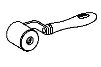
Roller
110 589 03 59 00
129 589 03 21 00
168 589 05 63 00

Locating tool
207 589 03 23 00
Repair materials
Number | Designation | Order number |
BR00.45-Z-1086-01A | Soft top frame sealing profile with metal core 35 m, SEALANT/butyl Bostik 1127 | A 005 989 12 71 10 |
BR00.45-Z-1099-02A | Adhesive tape/Acrylic Plus PT 1100 | A 008 989 20 85 |
BR00.45-Z-1125-02A | 4298 UV primer | A 007 989 96 71 10 |
BR00.45-Z-1025-04A | Cleaner | A 005 989 19 71 |
BR00.45-Z-1010-06A | Lubricant, rubber assembly 1 l | A 000 989 03 67 |
Referenced documents
- ar6830p4780ed Remove/install side paneling in rear
- ar6830p4800ec Remove/install side paneling in trunk
- ar7730p100202qa Install soft top support fastening gauge
- ar7737p1000ec Remove/install soft top hydraulic pump
- ar7737p4171qa Remove/install soft top mechanism hydraulic cylinder
- ar7737p4190qa Remove/install soft top bow hydraulic cylinder
- ar8885p200001ec Prepare sealing profile on roof frame for installation
- ar9140p0681eca Remove/install rear seat belts
- ar9160p0694ec Remove/install side airbag in the rear
- as0000z000901a Risk of injury. Moving parts can pinch, crush or, in extreme cases even sever extremities.
- as0000z001301a Risk of injury to skin or eyes from hydraulic fluid spraying out under pressure.Risk of poisoning from swallowing hydraulic fluid.
- as0000z001701a Risk of injury caused by scraping or cutting body parts on sharp vehicle parts