AR60.80-B-1000A | Remove/install cab | 12.02.16 |
Vehicle 682 with Cumbustion engine 376.930, 376.956, 372.961, 376.984
Vehicle 693 with Cumbustion engine 374.985, 377.941, 377.984, 377.960, 377.961
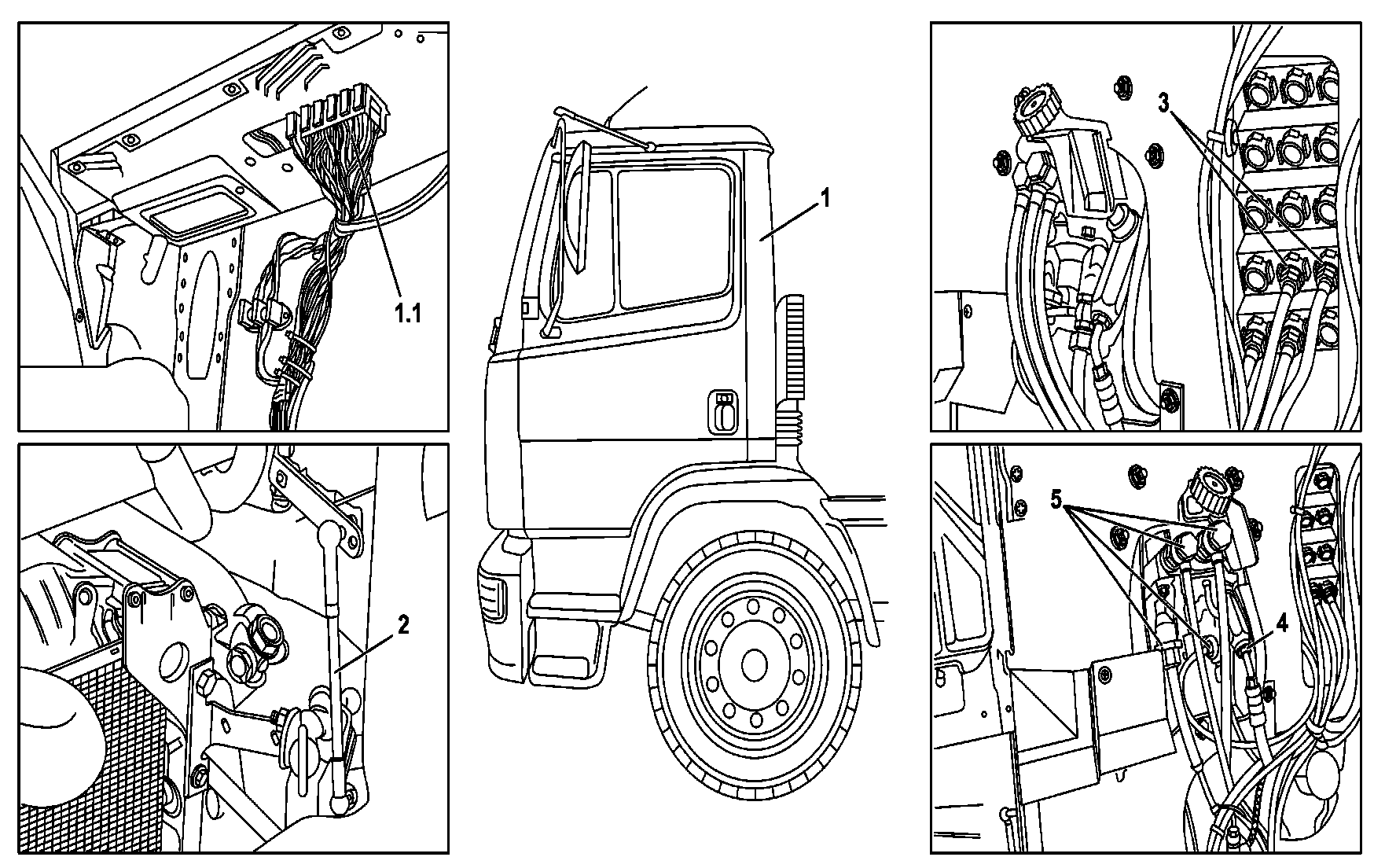
B60.80-0011-09
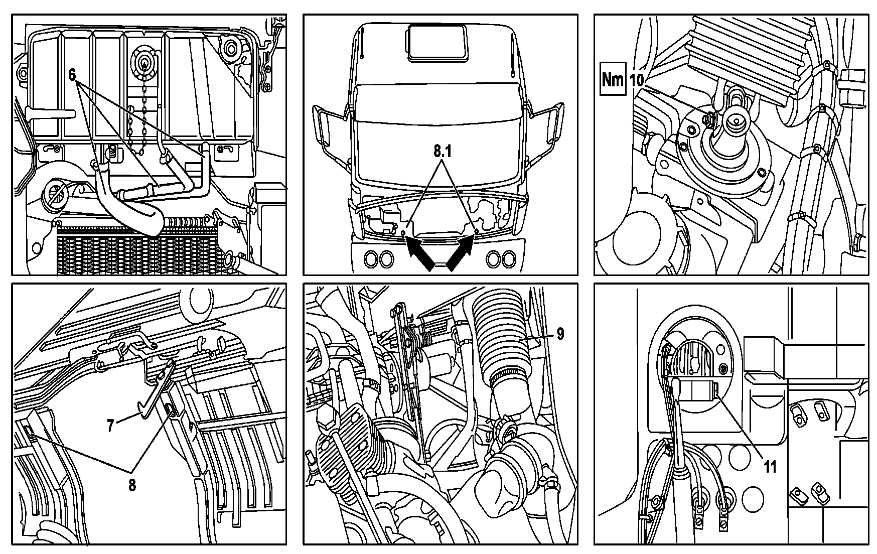
B60.80-0012-09
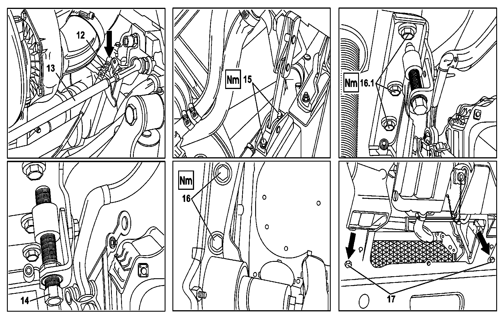
B60.80-0013-09
1 Cabin
1.1 Electric connectors
2 Acceleration rod
3 Parking brake tubes
4 Clutch cylinder hydraulic tubes
5 Service brake valve pneumatic tubes
6 Hoses
7 Safety hook
8/8.1 Holes to fit the cabin lifting device
9 Intake flexible tube
10 Cross bar articulation bot
11 Control rod
12 Idle speed regulation cable
13 Accelerator rod
14 Adjusting screw
15 Support rod fastening bolts
16/16.1 Cabin support fastening bolts
17 Bolts
| Remove and install | ||
Danger! | Risk of accident due to the accidental movement when the engine is operating. Risk of injury of crushing and burning for contact during start procedure or with functioning engine | Shim vehicle against involuntary movement. Wear work clothes well closed and attached to the body. Do not touch the heated or moving parts | |
All the self-locking nuts must be replaced once removed. | |||
All the plastic clamps cut during the removal must be replaced. | |||
All the sealing washers must be replaced at the installation, and their tightness must be checked after assembly. | |||
1 | Disconnect the negative cable from the battery or turn the general switch off | Loose the screw of the negative cable of the frame rail, avoiding to loose the battery terminals too. | |
2 | Open the front cover | ||
3 | Loose the electric connectors (1.1) from the chassis frame to the cabin and remove them downwards, through the cabin floor | Remove the front wall coating, inside the cabin, under the instruments cluster. | |
4 | Remove the acceleration rod (2) | ||
5 | Disconnect the junction plate, the parking brake compressed air tubes (3) | Attention: Previously depressurize the pneumatic circuit. | |
Danger! | Risk of poisoning by swallowing brake fluid. Risk of injury due to contact of the skin and eyes with the brake fluid. | Drain and store the brake fluid only in its original package. Wear protective gloves and goggles | |
6 | Loose the clutch actuation cylinder hydraulic tubes (4) | ||
7 | Loose the service brake valve pneumatic tubes (5) | Attention: Previously depressurize the pneumatic circuit. | |
Danger! | Risk of injuries on the skin and eyes, due to burns caused by spills of highly heated coolant. Risk of poisoning when ingesting coolant. | Open the cooling system only when its temperature is below 90ºC. Slowly unscrew lid and let out the excessive pressure. Never store coolant in beverage recipients. Always wear gloves, protective clothes and safety goggles. | |
8 | Drain the coolant by the orifices of the plugs existing in the engine block and in the radiator's lower box | Collect the coolant in an appropriate recipient and discard it in an environmentally friendly manner. | |
Install: Supply the system with new coolant in the specified quantity and duly prepared in the prescribed proportions. | |||
Indications about coolant | |||
| |||
Danger! | Risk of injuries and damages during the cabin tilting operation | During the cabin forward and rearwards tilting operation, do not go into the area in which the cabin tilts and adopt preventive measures to avoid that non-authorized persons go into it. Tilt the cabin always up to its final opening position | |
9 | Tilt the cabin up to 45° (1st stage) | ||
10 | \\Disassemble from the cabin the safety hook (7) together with the respective actuation lever | ||
11 | Install the cabin lifting device | At the rear part, fit the device in the holes (8) of the cabin longitudinal beam. | |
At the cabin front part, pass the device belts through the gap between the cabin and the external sun visor (if present), by the support handles below the windshield in order to avoid accidental fall of the cabin during its lifting operation. Insert the device pins in the holes (8.1) of the cabin front part. | |||
Cabin lifting device | |||
12 | In vehicles equipped with air filter under the cabin, remove the flexible intake tube (9) | ||
13 | Loose the cross bar articulation bolt (10) and remove the steering worm gear articulation | Install: Carefully fit the cross beam articulation in the steering worm gear's splined part, taking care to align the steering wheel. | |
| |||
14 | Disassemble from the gear lever the control rod (11) | In vehicles with chassis 693.023; disconnect the control cables at the gearbox, and at the installation carry out its adjustment. | |
15 | Remove from the engine the idle speed adjustment cable (12) | ||
16 | Break the seal and disconnect from the angle transmission the speedometer cable | ||
17 | Check the adjustment bolt ends for clearance (14) in the cabin stabilizer | If necessary, adjust the bolt until obtaining the desired clearance and the torsion bar tension. | |
18 | Disassemble from the chassis frame, the cabin support rod (15) | Conveniently fasten the support rod to the cabin to avoid interference during the assembly. | |
| |||
19 | Loose and remove from the cabin's lower front part the fastening bolt of the right (16) and left (16.1) support. | Make sure that the cabin is supported by the lifting device. | |
| |||
Danger! | Risk of death when tilting the cabin by an inappropriate manner. Risk of having parts of the body caught or smashed by the cabin downwards movement. | Use only approved lifting devices. Always check whether the supports used are safe. Never go or stay under the cabin when it is lifted | |
20 | Lift and remove the cabin | ||
21 | Install in reverse order |
Cab mounting
Número | Denominação | Type 682.0, 682.1, 688.2, 693.0, 693.1 | |||
BE60.80-B-1001-02A | Cabin locking adjustment distance (A) | mm | 120...150 | ||
Steering shaft
Número | Denominação | Chassis 384, 386, 388, 397, 660, 682, 688, 693, 694, 695, 696 | |||
BA46.10-B-1001-01A | Steering column cross bar | M8 | Nm | 30...35 | |
M10 | Nm | 60 | |||
Cab, cab mounting
Número | Denominação | Chassis 397.3; 682.0; 682.1; 688.2; 693.0; 693.1 except 693.154/193/194/196/197; 693.2; 693.3 | |||
BA60.80-B-1001-01E | Attachment of the cabin right and left front supports | M14 | Nm | 170...180 | |
BA60.80-B-1003-01E | Support rod bolt, in the chassis frame | M10 | Nm | 50...60 | |
Filling quantities for engine cooling
Número | Denominação | Engine 374.9 except 374.985 | Engine 374.985, 376.9 (aspirated engines) | |||
BF20.00-B-1001-01A | Cooling system - Approximate level | Do not mix products among the classes | Liters | 14 | 21 | |
Anti-corrosive/antifreeze CLASS MB 325.0, MB 325.3 | % | 50 | 50 | |||
Anti-corrosion product CLASS MB 312.0 | % | 10 | 10 | |||
Product already diluted | Anti-corrosion/antifreeze product CLASS MB 326.3 | Liters | 14 | 21 | ||
Pressure in the system | bar | 0,60...0,80 | 0,40...0,50 | |||
Vacuum in the system | bar | 0,10 | 0,10 | |||
Filling quantities for engine cooling
Número | Denominação | Engine 372.9, 376.9 (except aspirated diesel engines), 377.9 | |||
BF20.00-B-1001-01A | Cooling system - Approximate level | Do not mix products among the classes | Liters | 27 | |
Anti-corrosive/antifreeze CLASS MB 325.0, MB 325.3 | % | 50 | |||
Anti-corrosion product CLASS MB 312.0 | % | 10 | |||
Product already diluted | Anti-corrosion/antifreeze product CLASS MB 326.3 | Liters | 27 | ||
Pressure in the system | bar | 0,40...0,50 | |||
Vacuum in the system | bar | 0,10 | |||
Referenced documents
- ah2000b208001a Notes on coolant
- ap2000b0001a Replace coolant every 3 years
- ar2520b0140a Remove/install clutch operator protection valve
- ar6080b0010a Tilt cab to repair position, tilt back
- ar6080b100001a Unhook/hook in tilt mechanism
- ar8840b1000d Opening engine hood, moving to upright position and closing
- as0000b000501a Risk of accident from vehicle starting off by itself when engine running. Risk of injury (bruises and burns) resulting from working on the engine while it is being started or when it is running.
- as2000b000101a Risk of injury to skin and eyes suffering scalding from contact with hot coolantspray. Risk of poisoning from swallowing coolant.
- as4250b000101a Risk of poisoning from swallowing brake fluid. Risk of injury from skin and eye contact with brake fluid
- as6080b000101a Risk of injury caused by body parts being pinched or crushed as cab is tilted
- as6080b000201a Risk of death caused by improper lifting of cab. Risk of injury caused by body parts being trapped and crushed when lowering cab