
Shown on model 907.633 with code D03 (Roof and rear-end doors, high version), right side of vehicle |
1 | Lower rear side wall paneling behind wheel arch |
D63.10-1930-05

D60.00-A000-09
Shown on model 907 with code Q50 (Removable ball head for trailer coupling) |
2 | Rear-end doors | 5 | Frame seal | 7 | Right guide pin | ||
3 | Bumper | 6 | Left lock striker | 8 | Cover |

D60.00-A001-09
Shown on model 907 with code Q50 (Removable ball head for trailer coupling) |
9 | Electrical wiring harness |
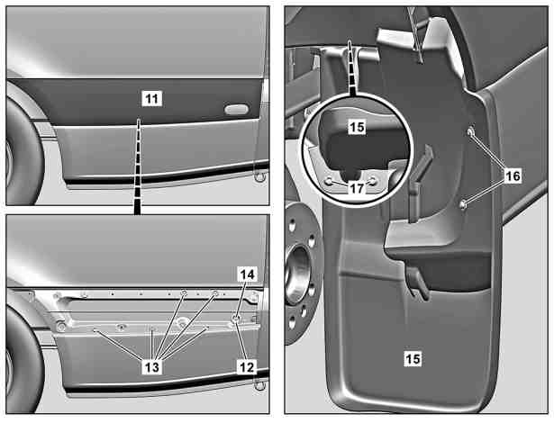
Shown on model 907 with code P48 (Rear mud flap), left side of the vehicle |
11 | Protective strip |
12 | Passage grommet |
13 | Plug |
14 | Connector |
15 | Dirt trap |
16 | Bolts |
17 | Nuts |
D60.00-A027-06
Danger | Risk of death when working on component parts and systems with U >= 30 V alternating voltage (AC) or U >= 60 V direct voltage (DC) | Do not touch damaged or defective live component parts and lines or non-insulated electrical connections and lines.Model 910.6 with engine 780.703 | |
Danger | Risk of death caused by vehicle slipping or toppling off of the lifting platform. | Align vehicle between vehicle lift columns and position the four support plates at the vehicle lift support points specified by the vehicle manufacturer. | |
Topical note | Notes on carrying out repair work in the vehicle interior | ||
| Remove/install | ||
1 | Remove respective wheel well trim. |
| |
2 | Remove respective side load compartment trim. |
| |
3 | Remove respective rear side wall trim in passenger compartment. |
| |
4 | Remove tie-down rail from side wall. |
| |
5 | Remove sealing frame (5) in repair area and position outside the working area. | ||
6 | Remove cover (8) for rear entrance. | ||
In the process, the left lock striker (6) and the right guide pin (7) are removed. | |||
7 | Remove bumper (3). |
| |
Model 907.6/7, 910.6 | |||
8 | Remove respective protective strip (11). | ||
9 | Remove respective feed-through grommet (12). | Model 907.6/7, 910.6 | |
To do so, position connector (14) with feed-through grommet (12) outside the working area in the vehicle interior. | |||
10 | Remove respective plugs (13). | The number of plugs (13) may vary depending on the body length. | |
11 | Remove respective mud flap (15). | Model 907.6/7, 910.6 | |
For this purpose, remove screws/bolts (16) and remove nuts (17). | |||
12 | Remove respective rear wheel. | ||
13 | Remove electrical wiring harness (9) and position outside the working area. | ||
14 | Remove vent flap from the respective lower section of corner pillar paneling. | ||
15 | Install in the reverse order. |
Referenced documents
- ah6800n000101s Notes on carrying out repair work in the vehicle interior
- ar4010d1100ts Remove/install wheels
- ar6830d0016ts Remove/install wheel well trim
- ar6830d1185ts Remove/install side load compartment paneling
- ar6830d1208tsr Remove/install rear side wall trim in passenger compartment
- ar6830d3520ts Remove/install rear entrance cover
- ar6850d8250ts Remove/install tie-down rail on sidewall
- ar8820d2200ts Remove/install rear bumper
- ar8820d2200tsb Remove/install rear bumper
- ar8880d1040ts Remove/install moldings
- as0000z001001a Risk of death caused by vehicle slipping or toppling off of the lifting platform.
- as0000z003501a Risk of death when working on component parts and systems with U >= 30 V alternating voltage (AC) or U >= 60 V direct voltage (DC)