
Front electro-pneumatic suspension |
1 | Front axle of the vehicle |
2 | Lower stringers of the frame |
H1 | Distance between the lower longitudinal member and the front axle |
B32.22-0066-05
B32.22-0004-09
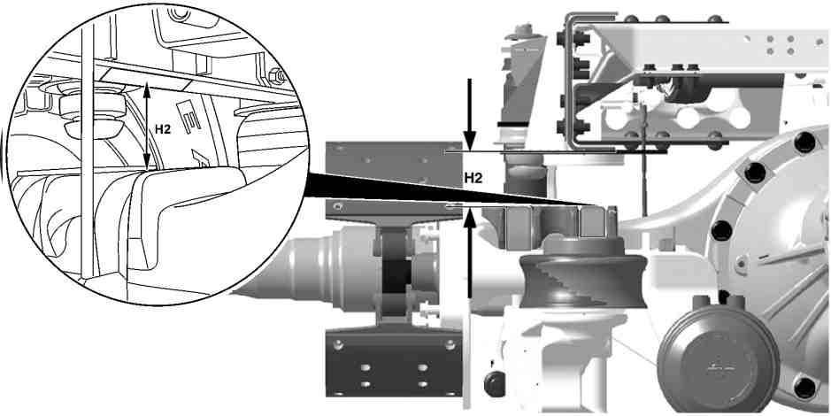
Rear electro-pneumatic suspension with the axles 746.218/225/270/271 |
H2 | Distance between the clamps of the axle and the lower face of the longitudinal member |

Rear electro-pneumatic suspension with the axles 746.973/974 |
1 | Axle U-bolt |
2 | Frame stringer |
3 | Bellows support |
H2 | Distance between the clamps of the axle and the lower face of the longitudinal member |
B32.22-0011-05
| Check | ||
Danger | Risk of death from lowering vehicle when working between wheels and body. Risk of injury from pinching or crushing when working on the air suspension. | Testing and repair work between the wheel and wheel arch or in the wheel well should only be performed if the vehicle is secured using suitable support fixtures to prevent it from lowering. | |
1 | Put the vehicle in a flat and leveled place, if possible with an appropriate ditch. | Apply parking brake and chock the wheels to prevent that the vehicle moves accidentally. | |
2 | Pressurize the air bellows to the normal working pressure of the vehicle | The pneumatic pressure must be kept above the minimum pressure required for the tests, otherwise the test equipments stops running. | |
.Minimum Pneumatic pressure in which ENR stops working in the rear axle | |||
.Minimum Pneumatic pressure in which ENR stops working in the front axle | |||
Calibrate | |||
3 | Loosen the lower fixation of the actuation rods of all sensors and block all sensors. Place the sensor actuation arms in the neutral point | ||
Block the level sensors to adjust the ENR system (ECAS). | |||
The calibration comprises the adjusting of the three height levels controlled by the level sensors. | |||
4 | Connect the diagnosis equipment in the vehicle diagnostic connector | ||
5 | Access the HHT WIN | ||
6 | Access the electronic control unit EN1 | On the function screen is shown: Activations. | |
7 | Access the option "Electromagnetic valve test | ||
8 | Access ”Front axle” on the “Activations” screen | ||
9 | Type F1 to put the vehicle at the “Normal height H1” | Check the values of the table on the screen | |
.Adjusting heights of the electro-pneumatic front suspension with ENR system (ECAS) : | |||
10 | Access ”Rear axle” on the “Activations” screen | ||
11 | Type F2 to put the vehicle at the “Normal height H2” | Check the values of the table on the screen. | |
.Adjusting height of the electro-pneumatic rear suspension with ENR system (ECAS) : | |||
12 | Fasten the rods of the level sensors on the lower fixing supports, and adjust by tightening the adjusting nuts | Do not remove the sensor locks to avoid erroneous measuring. | |
13 | Check the values shown on the screen in counts using the diagnosis equipment | Confirm on the screen the values of each sensor, and write them down in a sheet. | |
14 | Remove the sensor locks | In this position, the vehicle will be adjusted at the “Normal height H1 and H2". | |
15 | Access again “Front axle” in “Activations” | ||
16 | Type F1 to lower the right side of the vehicle to the “Lower height H1” | Read out the values in counts, and write them down in a sheet. | |
.Adjusting heights of the electro-pneumatic front suspension with ENR system (ECAS) : | |||
17 | Tap F2 to lower the vehicle on the right side to the “Bottom height H2” | Read out the values in counts, and write them down in a sheet. | |
.Adjusting height of the electro-pneumatic rear suspension with ENR system (ECAS) : | |||
18 | Put the vehicle again in the “Normal height” position | ||
19 | Put the vehicle at the position of “upper height H1 and H2 ” | ||
20 | Key on “Activations” and write down the values in Counts shown on the screen | ||
21 | Return to “Activations” and select the option “Parameterization” | ||
22 | Access the option "7" in Parameter and change to “3 Levels of Calibration” | ||
23 | Return on the screen “Functions”, and activate “Level of Calibration” | ||
24 | Enter the calibration values written down on the sheet | ||
25 | Select the option “Activations” and “Rear axle” | ||
26 | Access the option “Level adjustment” on the screen "Calibration", then “Front axle adjustment” | ||
27 | Enter the values read in counts | ||
28 | Access the option “Level adjustment” on the screen "Calibration", then “Rear axle adjustment” | ||
29 | Enter the values read in counts | ||
30 | Go back in the screen “Calibration”, access the screen “Level adjustment” | ||
31 | Access “Calibrate”, and type on “Enter” | The values will be transfered to the vehicle's electronic module. | |
With this operation the calibration is finished. | |||
32 | Turn on the ignition key and note the light on dashboard | After turning the contact switch OFF and ON, the height setting will adjust itself automatically. | |
If the light remains on: | |||
| |||
Carry out the calibration again. | |||
33 | After finishing the adjusting, disconnect the diagnosis equipment from the vehicle electronic control unit | ||
34 | Apply chemical seal on the adjustment nuts of the actuation rods of the sensors | ||
Calibrating in a simplified way | |||
35 | Connect the diagnosis equipment in the vehicle diagnostic connector | ||
To calibrate the level sensors, they should be unblocked and their rods must be adjusted. | |||
The simplified calibration facilitates in the cases where the vehicle has the sensors already regulated in the “Normal height”. | |||
36 | Access the HHT WIN | ||
37 | Access the electronic control unit EN1 | ||
38 | Select on the “Level calibration” screen and insert the calibration values from the table for the axles | .Adjusting height of the electro-pneumatic rear suspension with ENR system (ECAS) : | |
.Adjusting heights of the electro-pneumatic front suspension with ENR system (ECAS) : | |||
39 | Return to the “Calibration” screen and access the function “Calibrating” | ||
40 | Turn-off the ignition key to memorize the calibration values | ||
41 | Open and close the vehicle door | After this operation, the vehicle assumes, through the Electronic control unit, the normal calibration heights. | |
42 | After finishing the adjusting, disconnect the diagnosis equipment from the vehicle electronic control unit | ||
43 | Carry out a test route | Check the vehicle's behavior. |
Electronic Level Control (ENR) |
Number | Designation | Vehicle 634.0 with rear axle 746.973/974 | Vehicle 634.0 with rear axle 746.218/225/270/271 | |||
BE32.33-B-1001-01A | Adjusting heights of the electro-pneumatic front suspension with ENR system (ECAS) : | Normal height H1 | Height | mm | 110 | 110 |
Parameter | Counts | - | - | |||
Upper height H1 | Height | mm | 180 | 180 | ||
Parameter | Counts | - | - | |||
Lower height H1 | Height | mm | 50 | 50 | ||
Parameter | Counts | - | - |
Electronic Level Control (ENR) |
Number | Designation | Vehicle 634.0 with rear axle 746.973/974 | Vehicle 634.0 with rear axle 746.218/225/270/271 | |||
BE32.33-B-1004-01A | Adjusting height of the electro-pneumatic rear suspension with ENR system (ECAS) : | Normal height H2 | Height | mm | 120 | 114 |
Parameter | Counts | - | - | |||
Upper height H2 | Height | mm | 190 | 184 | ||
Parameter | Counts | - | - | |||
Lower height H2 | Height | mm | 60 | 54 | ||
Parameter | Counts | - | - |
Referenced documents
- ar3233b0011a Remove/install position sensor for level control
- as3222z000101a Risk of death from lowering vehicle when working between wheels and body. Risk of injury from pinching or crushing when working on the air suspension.