AR26.10-D-0020NG | Remove/install transmission | 23.5.11 |
TRANSMISSION 711.651 in MODEL 906 with ENGINE 271.951

D26.10-1145-09
1 Transmission
2 Bracket
3 Retaining clamp
4 Securing clamp
5 Remove clutch line
6 Central clutch release bearing
7 Shift cables
8 Exhaust bracket
11 Propeller shaft
B6/12 Speed sensor (on vehicles with code (J19) tachograph 1 day / 2 driver automatic (EU) or with code (JD1) EU digital tachograph or with code (JD2) EU digital tachograph with rpm and additional recorder)
G3/19x1 Connector of oxygen sensor downstream of CAT
G8/5x1 Connector of oxygen sensor upstream of catalytic converter
B6 Speed sensor (on vehicles without code (J19) Automatic 1 day / 2 driver tachograph (EC) or without code (JD1) EU digital tachograph or code (JD2) EU digital tachograph with rpm and additional recorder)
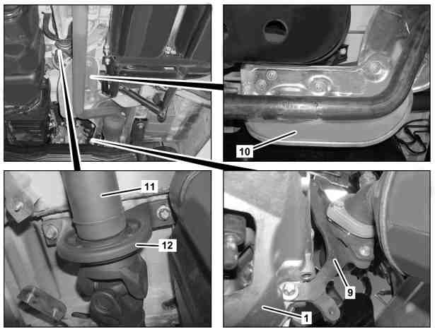
D26.10-1146-06
1 Transmission
9 Exhaust bracket
10 Heat shield
11 Propeller shaft
12 Propeller shaft center support bearing
Modification notes
20.5.11 | Value changed: Bolt, securing clip to frame floor assembly | Model 906 without code ZG1/ZG2/ZG3/ZG4 Model 906 with code ZG1/ZG2/ZG3/ ZG4 |
| Remove/install | ||
| Notes on self-locking nuts and bolts | ||
1 | Disconnect battery ground line | ||
2 | Lift/jack up vehicle | ||
3 | Drain transmission oil | When repairing transmission (1). | |
4 | Disconnect the connector of oxygen sensor upstream of CAT (G8/5x1) and connector of oxygen sensor downstream of CAT (G3/19x1) and unclip from bracket (2) and retaining clip (3) | ||
5 | Remove starter and hang up to one side with lines connected | ||
Danger! | Risk of poisoning caused by swallowing brake fluid. Risk of injury caused by brake fluid coming into contact with skin and eyes. | Only pour brake fluid into suitable and appropriately marked containers. Wear protective clothing and eye protection when handling brake fluid. | |
6 | Remove safety clip (4) and detach clutch line (5) | Collect brake fluid which runs out in a suitable container. Seal openings on clutch line (5) and central clutch release bearing (6) with stop plugs. | |
Installation: Replace seal ring of clutch line (5). | |||
| |||
| Brake fluid notes | ||
7 | Detach shift cables (7) from transmission (1) | Installation: Grease ball heads of shift cables (7). | |
Long-life grease | |||
8 | Remove lead seal from speed sensor (B6) | For vehicles with code (J19) Automatic 1 day / 2 driver tachograph (EU) or without code (JD1) EU digital tachograph or without code (JD2) EU digital tachograph with rpm and additional recorder | |
Installation: Replace lead seal. | |||
9 | Disassemble speed sensor (B6 or B6/12) from transmission (1) and hang up to one side with electrical line connected | Installation: Install new sealing ring. | |
10 | Detach exhaust bracket (8) | Installation: Check rubber mounts and replace if necessary. | |
| |||
11 | Detach exhaust bracket (9) | | |
12 | Remove heat shield (10) | Check spring washers for damage and replace if necessary. | |
13 | Remove securing bracket of propeller shaft (11) | ||
| |||
14 | Detach propeller shaft (11) at drive flange of transmission (1) and hang up to one side | | |
15 | Detach propeller shaft center support bearing (12) from underfloor and hang up to one side. | Secure propeller shaft (11) to prevent it from falling. | |
| |||
16 | Remove engine crossmember at rear | ||
17 | Support engine between oil pan and front axle carrier using a suitable block of wood | ||
18 | Secure transmission (1) against falling down with tensioning strap of transmission plate | ||
19 | Detach transmission (1) from engine, hang up electrical wiring harness for oxygen sensors to one side and pull out transmission (1) to rear using transmission jack. | Installation: Pay attention to installation position of electrical wiring harness for oxygen sensors. | |
Transmission jack, transmission platform gotis://H_00.10_01.0 | |||
| |||
20 | Release tensioning strap and remove transmission (1) from transmission jack | Aid of helper required. | |
21 | Check central clutch release bearing for damage | Replace central clutch release bearing if damaged. See | |
Remove/install central clutch operator | |||
22 | Install in the reverse order | ||
23 | Bleed clutch operating system | ||
24 | Check the clutch and shift mechanism for proper operation | If it is not possible to shift the transmission (1) through the gears easily, readjust the shift cables (7). See | |
Adjust shift cables (7) |
Complete manual transmission
Number | Designation | Trans-mission 711.651 | |
BA26.10-N-1001-01A | Bolt, manual transmission to engine | Nm | 38 |
Transmission housing
Number | Designation | Trans-mission | |
BA26.40-N-1019-01A | Bolt, exhaust bracket to transmission and exhaust | Nm | 23 |
Propeller shaft
Number | Designation | Model | ||||
BA41.10-N-1001-01B | Propeller shaft on transmission | M101 | Stage 1 | Nm | 15 | |
Stage 2 | ° | 90 | ||||
Screw headE14 | Stage 1 | Nm | 15 | |||
Stage 2 | ° | 70 | ||||
M121.5 | Screw headE14 | Stage 1 | Nm | 15 | ||
Stage 2 | ° | 50 | ||||
Screw headE18 | Stage 1 | Nm | 60 | |||
Stage 2 | ° | 60 | ||||
BA41.10-N-1004-01B | Bolt, retaining bracket to frame floor | M121.5 | Nm | 70 | ||
Propeller shaft
Number | Designation | Model | ||||
BA41.10-N-1001-01B | Propeller shaft on transmission | M101 | Stage 1 | Nm | - | |
Stage 2 | ° | - | ||||
Screw headE14 | Stage 1 | Nm | - | |||
Stage 2 | ° | - | ||||
M121.5 | Screw headE14 | Stage 1 | Nm | - | ||
Stage 2 | ° | - | ||||
Screw headE18 | Stage 1 | Nm | - | |||
Stage 2 | ° | - | ||||
BA41.10-N-1004-01B | Bolt, retaining bracket to frame floor | M121.5 | Nm | 70 | ||
Propeller shaft
Number | Designation | Model | ||||
BA41.10-N-1001-01B | Propeller shaft on transmission | M101 | Stage 1 | Nm | - | |
Stage 2 | ° | - | ||||
Screw headE14 | Stage 1 | Nm | - | |||
Stage 2 | ° | - | ||||
M121.5 | Screw headE14 | Stage 1 | Nm | 15 | ||
Stage 2 | ° | 50 | ||||
Screw headE18 | Stage 1 | Nm | 60 | |||
Stage 2 | ° | 60 | ||||
BA41.10-N-1004-01B | Bolt, retaining bracket to frame floor | M121.5 | Nm | 70 | ||
Propeller shaft center support bearing
Number | Designation | Model | ||
BA41.40-N-1001-01A | Bolt, propeller shaft intermediate bearing | M10 | Nm | - |
M121.5 | Nm | 135 | ||

Set of stop plugs
129 589 00 91 00
Repair materials
Number | Designation | Order number |
BR00.45-Z-1001-06A | Long-life grease | A 000 989 63 51 11 |
Referenced documents
- ah0000n000101a Notes on self-locking nuts and bolts
- ah4250p000101a Brake fluid notes
- ap2600d2601h Manual transmission - oil change
- ar0060d1000h Lift/jack up vehicle
- ar1530d7100ng Remove/install starter
- ar2210d1170sd Remove/install rear engine cross member
- ar2520d0070sd Bleed clutch operating system
- ar2520d0180sd Remove/install central clutch operator
- ar2660d662601a Detach/attach shift cables at transmission
- ar2660d6633a Adjust shift cables for manual transmission
- ar4110d005016a Remove/install retaining bracket
- ar5410d0003sd Disconnect/connect battery ground line
- as4250z000101a Risk of poisoning from swallowing brake fluid. Risk of injury from skin and eye contact with brake fluid