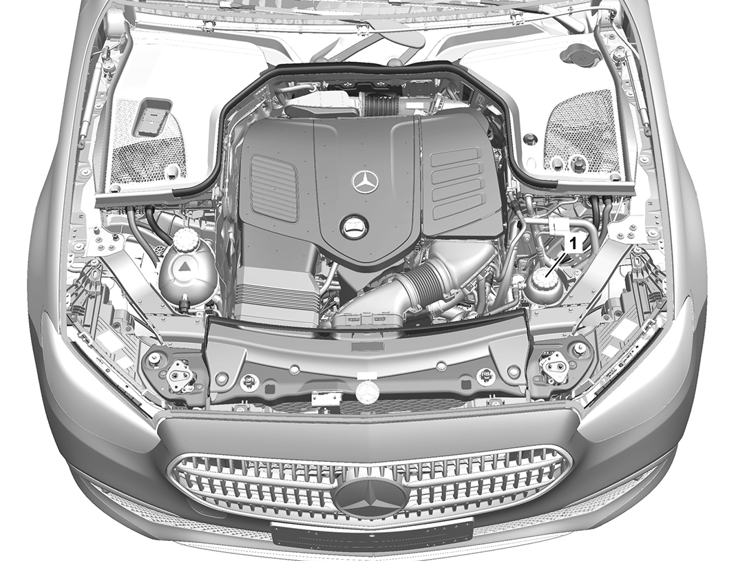
1 | Cap |
P20.00-A089-06
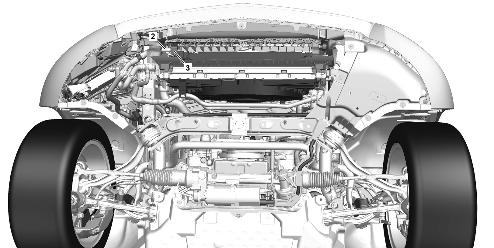
P20.00-A090-09
2 | Coolant hose | 3 | Air regulation system lower part |
Warning | Risk of injury due to fan starting unexpectedly | Do not reach into the rotation or hazard area of the fan. Wear closed and close-fitting work clothes. | |
Warning | Risk of injury. Skin or eye injuries may result when handling hot or glowing objects. | Wear protective gloves, protective clothing and safety glasses, if necessary. | |
Warning | Risk of injury to skin and eyes suffering scalding from contact with hot coolantspray. Risk of poisoning from swallowing coolant. | Do not open cooling system unless coolant temperature is below 90 °C. Open cap slowly and release the pressure. Do not pour coolant into beverage containers. | |
Topical note | Notes on avoiding damage through contamination and foreign objects | ||
Topical note | Notes on coolant | ||
Notes on coolant level | |||
Drain off | |||
1 | Open hood, carefully remove the cap (1) from the coolant expansion reservoir and release the overpressure. | ||
2 | Remove center engine compartment lining, front center engine compartment lining, and front right engine compartment lining. | ||
3 | Remove air regulation system lower part (3). | ||
4 | Remove coolant hose (2) from the cooler for the 48 V on-board electrical system and collect escaping coolant in a suitable container. | ||
5 | Install coolant hose (2) on the cooler for the 48 V on-board electrical system. | ||
6 | Install air regulation system lower part (3). | ||
Pour in | |||
7 | Connect vehicle diagnosis system and switch on ignition. | ||
| |||
8 | Start fill mode of the coolant circuit for the 48 V on-board electrical system. | ||
9 | Pour in the coolant and bleed the coolant circuit for the 48 V on-board electrical system. | ||
| |||
Engine 254 in model 213.073 | |||
Test pressure for pressure-testing the engine cooling system | |||
Cooler vacuum filling device | |||
Electric vacuum pump | |||
Pressure pump | |||
Test cap | |||
NTKL Adaption | |||
10 | End fill mode of the coolant circuit for the 48 V on-board electrical system. | ||
11 | Start bleeding routine of the coolant circuit for the 48 V on-board electrical system. | This involves actuating the coolant pumps to remove residual air from the coolant circuit. | |
If the bleeding routine was not completed successfully: | |||
| |||
Repeat bleeding routine of the coolant circuit for the 48 V on-board electrical system. | |||
12 | Switch off ignition and disconnect diagnostic system. | ||
| |||
13 | Check coolant level, correct if necessary. | Coolant mixing ratio | |
14 | Install center engine compartment lining, front center engine compartment lining, front right engine compartment lining. | ||
15 | Screw the cap (1) onto the coolant expansion reservoir. |


285 589 01 21 00
NTKL Adaption
210 589 00 91 00
Test cap
124 589 24 21 00
Pressure pump
285 589 02 21 00
Electric vacuum pump

285 589 00 21 00
Cooler vacuum filling device
Referenced documents
- ad0000p200004b Connect STAR DIAGNOSIS and read out fault memory
- ah0000p500001a Notes on avoiding damage through contamination and foreign objects
- ah2000n208001a Notes on coolant
- ah2000p114201cw Notes on coolant level
- ar2000p114204olc Pour in coolant and bleed cooling system
- ar2020p744101rq Open, close coolant line coupling
- ar6120p1105lwe Remove/install lower engine compartment lining
- as0000z000201a Risk of injury. Skin or eye injuries may result when handling hot or glowing objects.
- as2000z000101a Risk of injury to skin and eyes suffering scalding from contact with hot coolantspray. Risk of poisoning from swallowing coolant.
- as2040z000101a Risk of injury due to fan starting unexpectedly