
S07.14-2000-09
1 Vacuum pump
2 Middle screw/ left thread
3 Washer
4 Disc spring
5 Advance timer
6 Chain tensioner
7 Camshaft wheel
8 Timing chain
9 Washer
10 Stretch bolt
11 Cylinder head cover
12 Retainer
13 Sealing screw
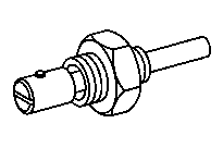
14 Arresting screw
15 Splined wrench
| Removing, installing | ||
1 | Remove the cylinder head cover (11) | ||
2 | Remove the vacuum pump (1) | ||
3 | Slacken the middle screw (2) | | |
4 | Position the engine in the 1st cylinder at 15° after PMS | Rotate the engine by the crankshaft | |
5 | Mark the camshaft wheel (7) with respect to the timing chain (8) | with felt-tip pen | |
6 | Remove the chain tensioner | ||
7 | Unscrew the stretch bolt (10), withdraw the washer (9) and the camshaft wheel (7) | If necessary, using a suitable drift punch, brace the camshaft by the camshaft wheel (7) | |
| |||
Installation: The camshaft wheel (7) and the timing chain (8) marks must coincide (arrows), pay attention to the cylndrical pin (arrow) | |||
8 | Unscrew the middle screw (2) and take out together with the washer (3) and disc spring (4) | Left thread | |
9 | Unscrew the sealing screw (13) of the injection pump and take out with the retainer (12) | | |
10 | Insert the arresting screw (14) in the sealing bore until it clicks in and then tighten it. | With the arresting screw (14) fitted there is a distance (arrow) between the pin collar and the screw | |
| |||
with manual force | |||
Installation: Before tightening the setscrew of the advance timer and the camshaft wheel, unscrew the arresting screw from the injection pump and insert the sealing plug again. | |||
11 | Push the timing chain (8) backwards and withdraw the advance timer (5) | Installation: Pay attention to the notching teeth in the advance timer (5) and in the injection pump housing journal. | |
12 | Fit the splined wrench (15) on the injection pump and with a slight to and fro movement, test the locking of the arresting screw (14) | | |
13 | Installation in reverse order | ||
14 | Test the delivery start and correct the adjustment if necessary | Positional sensor RIV method | |
or | |||
RIV method with digital instrument |
Test values camshaft screws
Number | Designation | Engine 601.942/970 | ||
BE05.20-N-1001-05A | Stretch bolt camshaft wheel | Thread diameter | M | 11 |
Max. rod length (L) | mm | 53.6 | ||
Fig. see | – | |||
Camshaft
Number | Designation | Engine 601.942/ | ||
BA05.20-N-1001-01F | Camshaft sprocket/flange shaft to camshaft | 1st stage | Nm | 25 |
2nd stage | ° | 90 | ||
Diesel injection system in general
Number | Designation | Engine 601.942 601.970 | |
BA07.11-N-1008-01A | Middle screw advance timer in injection pump left thread | Nm | 46 |
BA07.11-N-1009-01A | Sealing screw in regulator body | Nm | 30 |

601 589 00 08 00
601 589 05 21 00
Arresting screw
Splined wrench
Referenced documents
- ar0100s0120b Rotate the engine from the front part of the crankshaft
- ar0120s5014b Removing, installing cylinder head cover
- ar0510s7800b Removing, installing chain tensioner
- ar0711s8240a Check start of delivery (position sensor governor impulse method)
- ar0711s8244a Check start of delivery (digital test equipment governor impulse method)
- ar4305s1320a Removing and installing the vacuum pump