
B42.60-0204-12
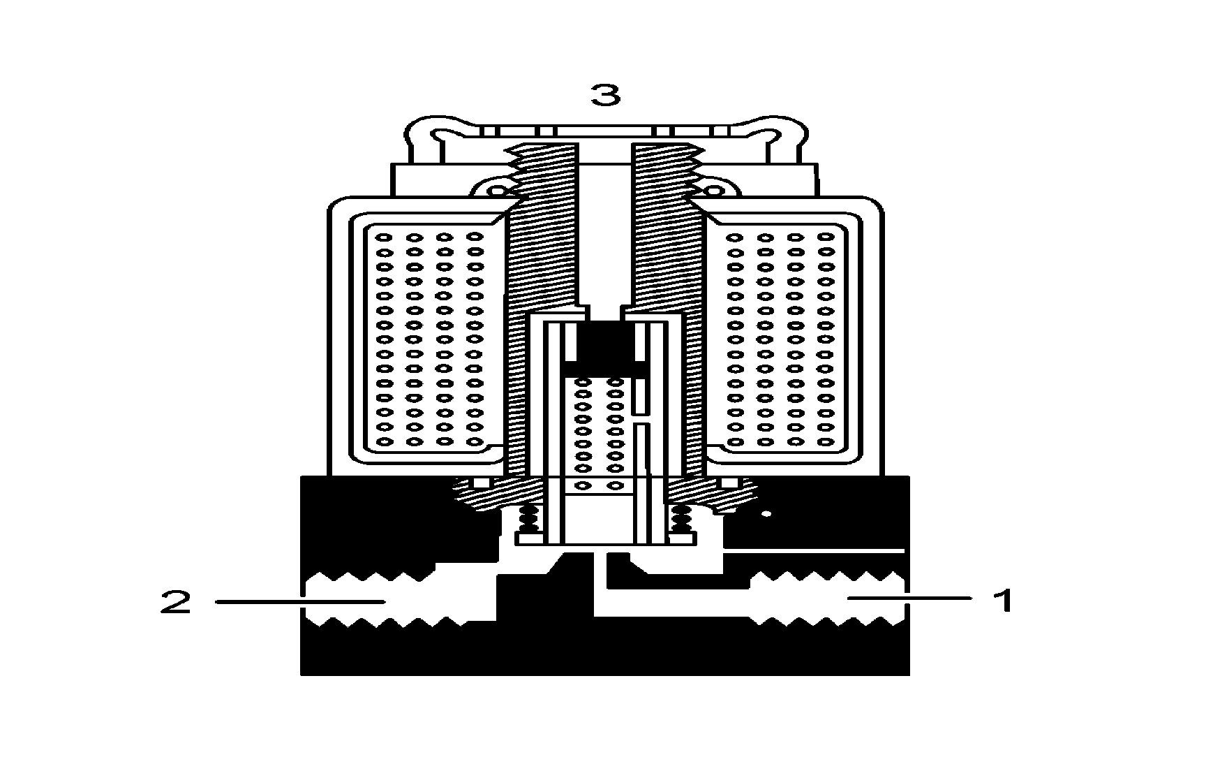
B42.60-0200-02
1 | Visual check | Accessories of the test stand: | |
Check the valve for outside damages and the condition of the coil, connector and electric wires. | |||
2 | Connect the valve to the test stand | Fast coupling (1) of the test stand on the connection 1 (ENT.) or (IN.) | |
Fast coupling (3) of the test stand on the connection 2 (CIL.) or (CYL.) | |||
3 | Prepare for test | Before connecting the electric wires on the electro-pneumatic valve connector, the operator must make sure the electric current to be utilized corresponds to the tension and to the amps required for its actuation. Connect the coil connector wires to a 12 V or 24 V battery. The battery must be with normal charge. | |
4 | Close valves C, V and 3 Apply 10 bar pressure to the test stand supply circuit by means of the reduction valve D. Observe the applied pressure on gage V. | ||
5 | Apply 10 bar pressure on circuit 1 by means of the regulating valve FN1. Observe the pressure applied to gauge 1. | ||
6 | Energize and de-energize the solenoid of the electro-pneumatic valve from 10 to 12 times to ensure the seating of the inlet and discharge valves. | ||
7 | Test the tightness | ||
8 | With the electropneumatic valve at rest (de-energized), apply 10 bar pressure on circuit 1 by means of the regulating valve FN1. Observe the pressure applied to gauge 1. | ||
9 | Disconnect the port 2 of the valve. Apply neutral soap foam on port 2 and on the discharge to check for leaks. | ||
10 | Connect again the test stand connection on port 2. Energize the electro-pneumatic valve solenoid. The pressure at ports 1 and 2 will have to be 10 bar. Observe the pressure on gauges 1 and 3. In this position apply neutral soap foam to exhaust 3 and around the valve body to check for leaks. | Warning: If some leaks is detected, disassemble the valve and replace the damaged components. | |
11 | Test the operation | ||
12 | Air passage: With the solenoid of the electropneumatic valve de-energized, apply 10 bar in circuit 1 (ENT.) through the regulating valve FN1. Observe the pressure applied in the manometer 1. Energize the solenoid of the electropneumatic valve. The pressure in the circuit 2 (CIL.) indicated on gage 3 will have to be 10 bar. | ||
13 | Exhaust: With the circuits 1 and 2 with 10 bar pressure, de-energize the solenoid of the electro-pneumatic valve. The pressure in circuit 2 will have to decrease to “zero” bar with air flowing out in a continuous form through the discharge 3. Observe the pressure reduction on the manometer 3. | ||
14 | Remove the valve from the test stand | ||
15 | De-pressurize the circuits of the electro-pneumatic valve and disconnect the test hoses. | ||
16 | Disconnect the electric wires and disconnect the batteries. | ||
17 | Remove the valve from the workbench and plug the ports with appropriate plastic plugs. Fasten the coil connector. |