
Shown with engine 654.9 |
16 | Counterholder |
17 | Belt pulley |
S27.10-A010-81

Shown with engine 654.9 |
2 | Locking clamp |
3 | Bayonet coupling |
4 | Bolts |
5 | Electrical wiring harness |
6 | Bracket |
18 | Cover |
S27.10-A006-81

Shown with engine 654.9 |
1 | Automatic transmission |
7 | Mounting clip |
8 | AdBlue® line |
9 | Screw |
10 | Ground cable |
S27.10-A007-81

Shown with engine 654.9 |
1 | Automatic transmission |
11 | Screw |
12 | Torque converter |
S27.10-A008-05

Shown with engine 654.9 |
13 | Drive plate |
14 | Threaded unions |
15 | Holding device |
S27.10-A009-82

19 | Lifting device |
S27.10-A020-04
Warning | Risk of injury. Moving parts can pinch, crush or, in extreme cases even sever extremities. | No parts of the body or limbs should be within the operating area of mechanical components when moving components. | |
Caution | Risk of injury caused by scraping or cutting body parts on sharp vehicle parts | Always wear protective gloves when working on or near sharp and non-deburred vehicle parts. | |
Caution | Risk of injury to skin and eyes due to handling of transmission oil. Health risk caused by swallowing transmission oil | Wear protective gloves, protective clothing and safety glasses. | |
Topical note | General information on repair work on transmission | ||
Topical note | Notes on self-locking nuts and bolts | ||
Topical note | Information on preventing damage to electronic components due to electrostatic discharge | ||
Notes on automatic transmission | |||
| Remove | ||
1 | Switch on ignition. | Hood and doors must be closed. | |
2 | Release parking brake. | ||
3 | Shift automatic transmission (1) using selector lever to "Permanent N". | The display of the instrument cluster shows the message: | |
4 | Switch off ignition. | Do not remove the transmitter key. | |
5 | Remove ground line of battery. | ||
6 | Remove resonator box. |
| |
7 | Position counterholder (16) on belt pulley (17). | Model 447 with engine 654.9 with transmission 725.0 | |
Counterholder | |||
8 | Position a suitable tool on counterholder (16) to turn the crankshaft. | Model 447 with engine 654.9 with transmission 725.0 | |
Counterholder | |||
9 | Remove lower engine compartment paneling. | ||
10 | Remove underfloor paneling at left. |
| |
11 | Attach holding device (15). |
| |
Model 447 with engine 274 with transmission 725.0 | |||
Adjust support of holding device (15) to a gap of 10 mm relative to underside of timing case. | |||
Holding device | |||
12 | Remove propeller shaft. |
| |
13.1 | Remove transmission carrier. | Model 447 with engine 654.9 with transmission 725.0 | |
13.2 | Remove engine crossmember at rear. | Model 447 with engine 274 with transmission 725.0 | |
14 | Remove transmission mount. |
| |
15 | Remove heat shield. | ||
16 | Unlock securing clip (2) (arrow A) and remove bayonet coupling (3) from electrohydraulic controller unit. | ||
17 | Remove screws (4) and place electrical wiring harness (5) with holder (6) to one side. | ||
18.1 | Remove oil lines for automatic transmission oil cooling system. | Model 447 with engine 654.9 with transmission 725.0 | |
18.2 | Remove oil lines for automatic transmission oil cooling system and fasten outside the working area. | Model 447 with engine 274 with transmission 725.0 | |
19 | Remove automatic transmission oil cooler. |
| |
20 | Detach retaining clip (7) from torque converter housing and place AdBlue® line (8) to one side. | Model 447 with engine 654.9 with transmission 725.0 | |
21 | Remove cover (18). | ||
22 | Remove torque converter (12) from drive plate (13). | ||
Model 447 with engine 654.9 with transmission 725.0 | |||
Model 447 with engine 274 with transmission 725.0 | |||
Long wedge | |||
Model 447 with engine 654.9 with transmission 725.0 | |||
23 | Secure automatic transmission (1) on mounting plate. | ||
| 000 588 11 62 00 Major assembly mount | ||
| 000 588 10 62 00 Support plate | ||
24 | Remove starter, place to one side with lines still connected and secure. |
| |
Model 447 with engine 274 with transmission 725.0 | |||
25 | Remove ground line (10) and place to one side. | Unscrew screw (9) to do this. | |
26 | Remove screws (11). | ||
27 | Remove automatic transmission (1) together with torque converter (12). | Aid of helper required. | |
28 | Secure torque converter (12) with cable ties to prevent it from falling out. | ||
29 | Fasten automatic transmission (1) to assembly stand. | If further work is to be performed on the transmission (1). | |
| 000 588 00 31 00 Assembly stand for cars | ||
Commercially available devices/tools | |||
Lifting device | |||
Support fixture | |||
30.1 | Drain automatic transmission fluid from torque converter (12). | If the torque converter (12) is removed or replaced. | |
| |||
30.2 | Drain automatic transmission fluid from automatic transmission (1). | If the automatic transmission (1) is replaced or if further work is carried out on the automatic transmission (1). | |
31 | Move automatic transmission (1) to vertical position, remove cable ties and remove torque converter (12). | If the torque converter (12) is replaced or if it has to be removed for further work on the automatic transmission (1). | |
Direct torque converter housing upwards. | |||
Assembly device | |||
| Clean | ||
32 | Remove corrosion from crankshaft. |
| |
Assembly cleaner | |||
| Check | ||
33 | Check threaded unions (14) in drive plate(13). | If the threaded unions (14) are loose or damaged, | |
| |||
replace drive plate(13). | |||
| |||
| |||
| Install | ||
34 | Insert torque converter (12) and secure with cable ties to prevent it from falling out. | If the torque converter (12) was removed. | |
Commercially available devices/tools | |||
Protrusion of torque converter to torque converter housing | |||
Long-life grease | |||
Parallel support | |||
Support fixture | |||
Assembly device | |||
35 | Attach lifting device (19) to automatic transmission (1), remove automatic transmission (1) from assembly stand using an engine hoist and secure on mounting plate. | If the automatic transmission (1) was secured to the assembly stand. | |
| 000 588 11 62 00 Major assembly mount | ||
| 000 588 10 62 00 Support plate | ||
| 000 588 00 31 00 Assembly stand for cars | ||
| |||
Commercially available devices/tools | |||
Lifting device | |||
36 | Remove cable ties from torque converter (12). | ||
37 | Position automatic transmission (1) together with torque converter (12) into installation position. | ||
38 | Screw in screws (11). | Screw, torque converter housing to timing case/crankcase | |
39 | Position and attach ground line (10). | To do so, screw in screw (9). | |
Screw, torque converter housing to timing case/crankcase | |||
40 | Install starter. |
| |
Model 447 with engine 274 with transmission 725.0 | |||
41 | Mount torque converter (12) onto drive plate (13). | ||
Topical note | Notes on threaded connections fastened using a tightening angle-based tightening process | ||
Model 447 with engine 654.9 with transmission 725.0 | |||
Screw/bolt, torque converter to drive plate | |||
Model 447 with engine 274 with transmission 725.0 | |||
Long wedge | |||
Model 447 with engine 654.9 with transmission 725.0 | |||
42 | Install cover (18). | ||
43 | Position AdBlue® line (8) and clip retaining clip (7) onto torque converter housing. | Model 447 with engine 654.9 with transmission 725.0 | |
44 | Install automatic transmission oil cooler. |
| |
45.1 | Install oil lines of automatic transmission oil cooling system. | Model 447 with engine 654.9 with transmission 725.0 | |
45.2 | Attach oil lines for automatic transmission oil cooling system. | Model 447 with engine 274 with transmission 725.0 | |
46 | Position holder (6) with electrical wiring harness (5) and attach. | Screw in screw/bolts (4) to do this. | |
47 | Attach bayonet coupling (3) to electrohydraulic controller unit and lock securing bracket (2). | ||
48 | Install heat shield. | ||
Bolt, leaf spring for heat shield to transmission housing | |||
Bolt, heat shield to oil pan | |||
49 | Install transmission mount. |
| |
50.1 | Install transmission carrier. | Model 447 with engine 654.9 with transmission 725.0 | |
50.2 | Install engine crossmember at rear. | Model 447 with engine 274 with transmission 725.0 | |
51 | Install propeller shaft. |
| |
52 | Remove holding device (15). |
| |
Model 447 with engine 274 with transmission 725.0 | |||
Holding device | |||
53 | Remove tool for turning crankshaft from counterholder (16). | Model 447 with engine 654.9 with transmission 725.0 | |
Counterholder | |||
54 | Remove counterholder (16) from belt pulley (17). | Model 447 with engine 654.9 with transmission 725.0 | |
Counterholder | |||
55 | Install resonator box. |
| |
56 | Install ground line of battery. | ||
57 | Read out and delete fault memory. | ||
| |||
Do not yet remove vehicle diagnosis system. | |||
58 | Fill automatic transmission (1) with automatic transmission fluid. | ||
Do not yet remove vehicle diagnosis system. | |||
59 | Perform transmission adaptation with vehicle diagnosis system. | If automatic transmission (1) has been replaced or repaired. | |
| |||
Do not yet remove vehicle diagnosis system. | |||
60 | Reset service life data for torque converter lockup clutch using diagnostic system. | If torque converter (12) has been replaced. | |
| |||
61 | Remove vehicle diagnosis system. | ||
Warning | Risk of accident from vehicle starting off by itself when engine running. Risk of injury (bruises and burns) resulting from working on the engine while it is being started or when it is running. | Secure vehicle to prevent it from starting off by itself. Wear closed and snug-fitting work clothes. Do not touch hot or rotating parts. | |
62 | Conduct engine test run and check automatic transmission (1) for proper operation and leak tightness. | ||
63 | Install underfloor paneling at left. |
| |
64 | Install lower engine compartment paneling. |


725 589 00 40 00
Support fixture
724 589 02 63 00
Lifting device
447 589 00 62 00
Holding device
001 589 65 09 00
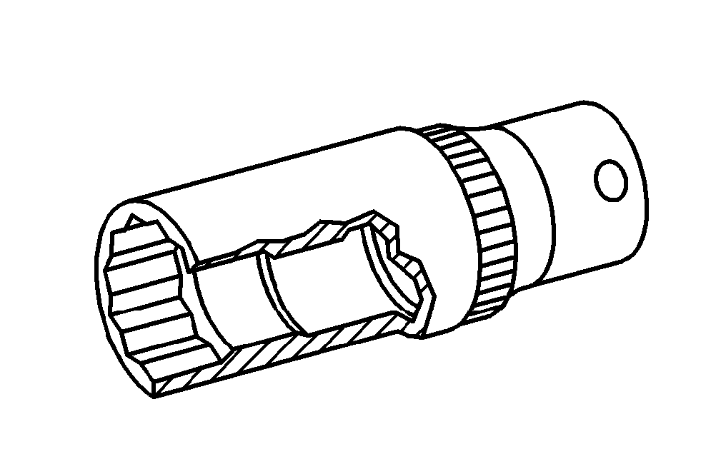
Socket wrench bit


168 589 03 21 00
Parallel support
725 589 01 31 00
Assembly device
115 589 03 59 00
Long wedge
654 589 00 40 00
Counterholder
Henviste dokumenter
- ad0000s200004e
- ah0000n000101a Oplysninger om selvlåsende bolte og møtrikker
- ah0000p002001a Oplysninger om skrueforbindelser, som er fremstillet efter den drejevinkelstyrede tilspændingsmetode
- ah2700s100001ps Generelle oplysninger om reparationsarbejde gearkasse
- ah2719p000101nkb Oplysninger om automatgearkasse
- ah2719p000101nkb
- ah5400p000101a Oplysninger med henblik på at undgå skader på elektroniske komponenter på grund af elektrostatisk afladning
- ap2700s2702eg Automatgearolie- og oliefilterskift
- ar0110s240004e
- ar0110s240018ea
- ar0320s100001ea
- ar0330s8003ea
- ar0330s8003eg
- ar0920s0010ea
- ar1530s7100eb
- ar1530s7100eg
- ar2210s0006e
- ar2210s0007e
- ar2210s1170e
- ar2700s0270ea
- ar2710s060001ea
- ar2710s7031ea
- ar2710s7031ea
- ar2720s000101ea
- ar2720s000101ea
- ar2720s050001ea
- ar2740s070002e
- ar2755s0600ea
- ar2755s0600eg
- ar2755s1000ea
- ar4110s0050e
- ar5410s0003e
- ar5410s0003e
- ar6120s1105e
- ar6120s1105e
- ar6130s1001e
- as0000z000501a Fare for ulykke ved automatisk igangsætning når motoren kører. Fare for personskade på grund af knusning og forbrænding, hvis der arbejdes mens motoren startes eller kører
- as0000z000901a Fare for personskade som følge af klemning af legemsdele, i værste fald fare forafskæring af legemsdele ved indgreb i mekanikken
- as0000z001701a Fare for personskade på grund af snitsår eller hudafskrabninger grundet skarpkantede køretøjsdele
- as0040z000101a Fare for personskade på hud og øjne ved håndtering af gearolie. Sundhedsfare ved indtagelse af gearolie
- ws0100n3028b
- ws0100p0092b
- ws2600p3309b