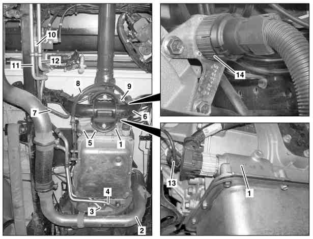
1 | Automatic transmission |
2 | Exhaust pipe |
3 | Transmission oil line |
4 | Transmission oil line |
5 | Bolts |
6 | Crossmember |
7 | Compressed-air line |
8 | Selector lever Bowden cable |
9 | Electrical wiring harness |
10 | Threaded connection |
11 | Transmission oil line |
12 | Transmission oil line |
13 | Electrical connector |
14 | Electrical connector |
D27.10-1124-06
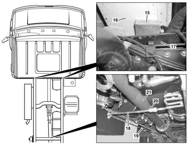
15 | Wooden block |
16 | Cab |
17 | Vehicle frame |
18 | Compressed-air line |
19 | Threaded connection |
20 | Threaded connection |
21 | Propeller shaft |
D27.10-1125-06

D27.10-1126-09
1 | Automatic transmission | 25 | Nut | 29 | Screw | ||
6 | Crossmember | 26 | Gearshift lever | 30 | Screw | ||
22 | Timing case | 27 | Shift shaft | 31 | Tensioning straps | ||
23 | Turning device | 28 | Nut | 32 | Screw | ||
24 | Screw |
| Remove/install | ||
Notes on automatic transmission | Transmission 723.332 in model 668, 670 with engine 900.917/918/919 | ||
1 | Move selector lever to "N" position and secure vehicle to prevent it from rolling away | ||
Danger | Risk of fire/risk of explosion due to short circuit and escaping oxyhydrogen gas. Risk of (burn) injury caused by caustic burns to eyes, skin and mucous membranes from battery electrolyte/mist, short circuit and arcing. Risk of poisoning caused by swallowing battery electrolyte or absorption of lead through the skin or orifices. Risk of death due to voltage U >= 30 V AC and U >= 60 V DC. | No fires, sparks, open flames or smoking. Wear acid-resistant gloves, clothing and glasses. Only pour battery acid into suitable and appropriately marked containers. | |
2 | Disconnect ground line from battery | ||
Topical note | Notes on battery | ||
Installation: Code code-protected devices and set time. | |||
3 | Remove maintenance hood | Installation: Do not install maintenance hood until after leak test. | |
4 | Remove compressed-air line (7) from compressor | ||
5 | Remove exhaust pipe (2) | ||
6 | Remove filler pipe of automatic transmission (1) | ||
7 | Detach compressed-air line (7) from threaded connection (10), remove and check for carbonization | If there is carbonization, also check compressed-air lines between compressor, compressed-air drier and 4-circuit protection valve; replace carbonized parts if necessary. | |
8 | Disconnect Electrical connection (13) | Installation: Replace lead seal of electrical connector (13). | |
9 | Disconnect electrical connector (14) and expose electrical wiring harness (9) | ||
10 | Unscrew screws (5) and remove selector lever cable (8) with holder from automatic transmission (1) | Check adjustment of selector lever cable (8), adjust if necessary. | |
| |||
Adjust selector cable | |||
11 | Drain transmission oil | ||
| |||
12 | Disconnect transmission oil lines (3, 4) from transmission oil lines (11, 12) and remove from automatic transmission (1) | Mark transmission oil lines (3, 4) relative to transmission oil lines (11, 12) and seal connections with suitable stop plugs. | |
13 | Position suitable wooden blocks (15) on right and left between cab (16) and vehicle frame (17) | The wooden blocks (15) prevent the cab (16) from lowering. | |
14 | Detach compressed-air line (18) from threaded connection (20), release at threaded connection (19) and swivel downward | ||
15 | Detach propeller shaft (21) from automatic transmission (1) and propeller shaft center support bearing, and tie to one side | ||
Do not remove propeller shaft (21) from rear axle. | |||
16 | Remove cap from timing case (22) and attach turning device (23) | Inspection hole cap to timing case | |
Turning device | |||
17 | Remove screws (24) | To do so, turn engine using turning device (23) until a torque converter screw (24) is visible through the assembly hole in the timing case (22). | |
Screw/bolt, torque converter to drive plate | |||
Turning device | |||
18 | Support engine at timing case (22) using pit hoist | This prevents the engine from tilting back when the automatic transmission (1) is removed. | |
19 | Unscrew nut (25) and remove gearshift lever (26) from shift shaft (27) | ||
20 | Position transmission jack with transmission plate under automatic transmission (1), and support automatic transmission (1) on both sides in area of oil pan screws using a suitable base, e.g. wooden blocks | | |
21 | Secure automatic transmission (1) to transmission plate using tensioning straps (31) to prevent it from falling down | ||
22 | Remove screws (29, 30) | Bolt, rear mounting console to transmission mount | |
Bolt/nut, transmission mount crossmember to longitudinal member | |||
23 | Push crossmember (6) as far backward as possible and simultaneously swivel upward at transmission mount | ||
24 | Remove screws (32) | Bolt, automatic transmission to crankcase | |
25 | Pull automatic transmission (1) backward using transmission jack and lower | | |
Secure torque converter with cable ties to prevent it from falling out. | |||
Installation: Clean centering pin on torque converter and grease lightly. | |||
Long-life grease | |||
26 | Install in the reverse order | ||
Warning | Risk of accident from vehicle starting off by itself when engine running. Risk of injury (bruises and burns) resulting from working on the engine while it is being started or when it is running. | Secure vehicle to prevent it from starting off by itself. Wear closed and snug-fitting work clothes. Do not touch hot or rotating parts. | |
27 | Start engine and check transmission oil level using oil dipstick, correct if necessary, then switch off engine | ||
| |||
28 | Check automatic transmission (1) for leak tightness |

904 589 04 63 00
Turning device
Henviste dokumenter
- ah2719p000101nkb Oplysninger om automatgearkasse
- ah2719p000101nkb
- ah5410p000101a Oplysninger om batterier
- ah5410p000101a
- ap2700d2702d Automatgearolie- og oliefilterskift
- ar2710d7010ad
- ar2760d012001ad
- ar4110d0050a
- ar4910d5530ad
- as0000z000501a Fare for ulykke ved automatisk igangsætning når motoren kører. Fare for personskade på grund af knusning og forbrænding, hvis der arbejdes mens motoren startes eller kører
- as5410z000101a Brand-/eksplosionsfare på grund af kortslutning og udsivende knaldgas. Forbrændingsfare/fare for personskade ved ætsning af øjne, hud og sliminder på grund af batterielektrolyt/-tåge, kortslutning og lysbuepåvirkning. Fare for