


285 589 01 21 00
NTKL Adaption
210 589 00 91 00
Test cap
124 589 24 21 00
Pressure pump
285 589 02 21 00
Electric vacuum pump

285 589 00 21 00
Cooler vacuum filling device
Ventilate the engine cooling system only on a cold engine.
The drainage container for the NTKL adaptation (13) must be emptied before beginning work.
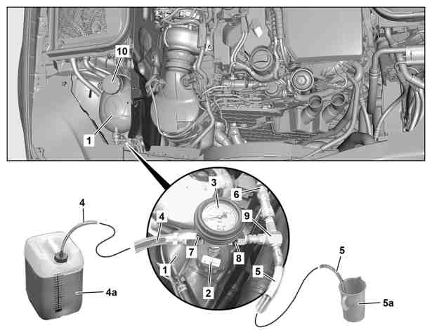
1 | Bring coolant reservoir (4a) of the vacuum-type cooling system filler to the same height as the coolant expansion reservoir (1). |
2 | Take off cooling system cap (10) and mount tester cap (2) on coolant expansion reservoir (1). |
3 | Connect pressure pump to tester cap (2). |
4 | Apply test pressure to engine cooling system for 2 min. . |
Do not exceed the test pressure. |
In the event of pressure loss: | |
| |
Perform visual check of coolant-conducting component parts. |
5 | Remove pressure pump. |
6 | Attach the control unit (3) to the tester cap (2). |
7 | Attach venturi nozzle (9) to control unit (3). |
8 | Close drain valve (8) and feed valve (7). |
9 | Fit feed hose (4) for coolant on coolant reservoir (4a). |
In order to avoid suctioning air into the coolant reservoir (4a), and to verify the filling capacity of the engine cooling system in the vehicle, always completely fill up the coolant reservoir (4a). |
10 | Insert waste air hose (5) into an empty container (5a). |
11 | Connect compressed-air hose (6) to venturi nozzle (9) and apply pressure. |
The overpressure in the compressed-air supply system must be at least 8 bar so that sufficient vacuum can be generated by the venturi nozzle (9). |
12 | Open drain valve (8). |
A vacuum is created in the engine cooling system. |
13 | Open feed valve (7) until feed hose (4) has filled with coolant and then close feed valve (7) again. |
14 | Close drain valve (8) if display of control unit (3) is in green area. |
15 | Remove compressed-air hose (6) from venturi nozzle (9) and monitor whether vacuum remains stable for 30 seconds. |
If this is not the case. | |
| |
Check hoses and connections for damage, repair if necessary and again create a vacuum. |
Shown on model 213 with engine 654 |
P20.00-2597-06
P20.00-2497-09
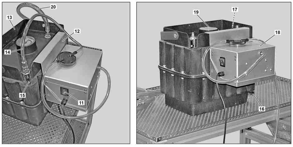
16 | Move switch (11) of electric vacuum pump (18) to 0 position. |
17 | Connect positive and negative terminals of electric vacuum pump (18) to a suitable 12 V voltage source. |
Observe polarity of the positive and negative terminals of the electrical vacuum pump (18). |
18 | Hook holder (12) into NTKL adaptation (13). |
19 | Connect hose (14) to NTKL adaptation (13). |
20 | Close stopcocks (15, 16, 17). |
21 | Connect hose (20) to the NTKL adaptation (13). |
22 | Decouple venturi nozzle (9) and replace with hose (20). |
23 | Switch on electric vacuum pump (18) and open stopcock (15). |
24 | Open drain valve (8). |
Feed valve (7) must remain closed. |
Evacuate entire engine cooling system for 5 min. The pointer of the vacuum indicator (19) must be above the -0.9 bar mark. |
25 | Close drain valve (8). |
26 | Switch off electric vacuum pump (18). |
Place switch (11) of the electrical vacuum pump (18) in 0 position. |
27 | Remove hose (14) and reduce vacuum in NTKL adaptation (13) until vacuum display (19) shows 0.0 bar. |
28 | Check entire engine cooling system for leak tightness by performing a visual check for 30 s. |
29 | Open feed valve (7). |
The engine cooling system is filled. |
Filling is complete when the control unit (3) shows 0.0 bar. |
30 | Open drain valve (8) if coolant is no longer suctioned. |
31 | Remove control unit (3) along with all connections and tester cap (2). |
32 | Correct coolant level in coolant expansion reservoir (1). |
33 | Attach cooling system closure cap (10) on coolant expansion reservoir (1). |