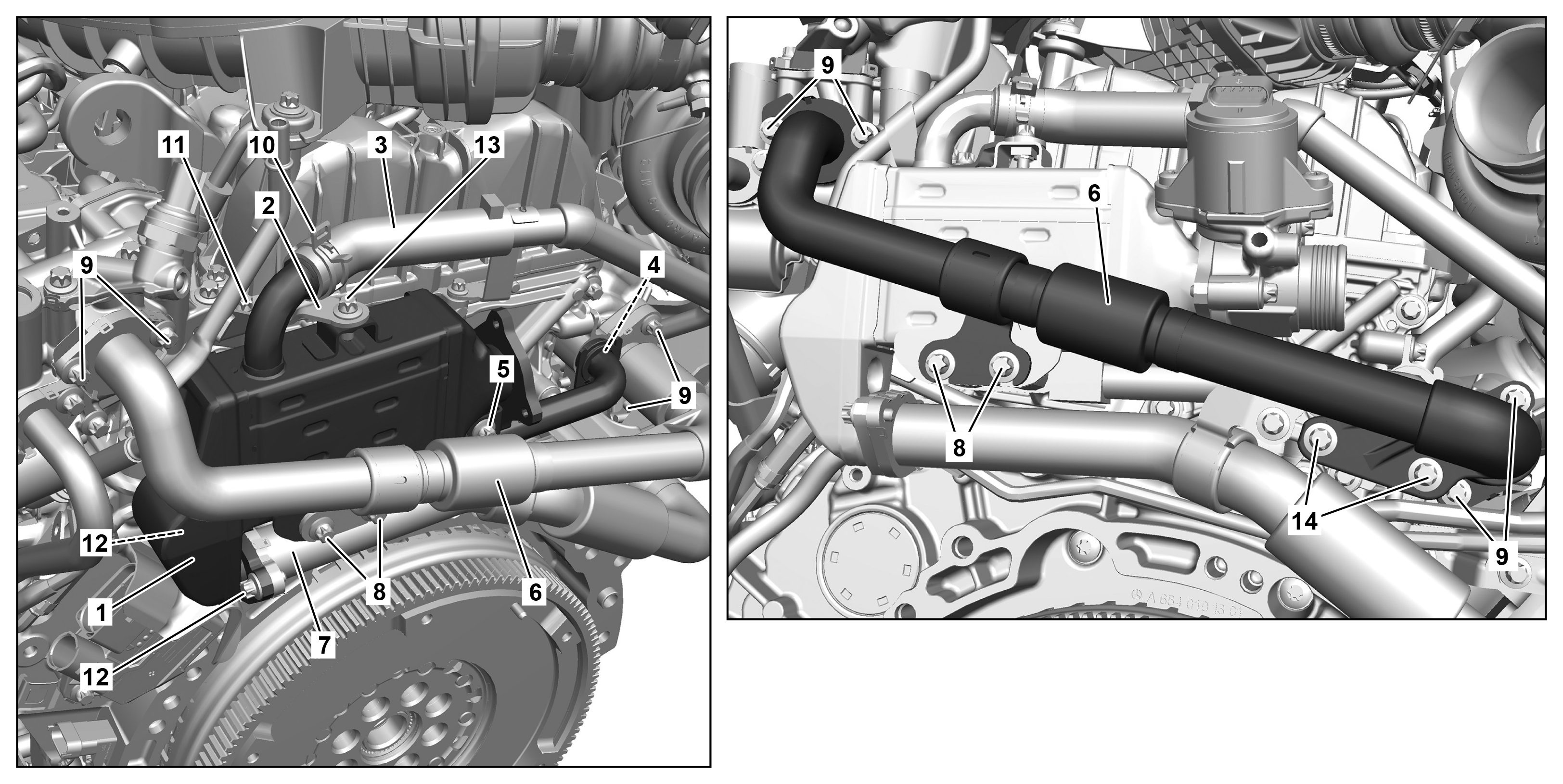
P14.20-A022-09
1 | Low pressure exhaust gas recirculation cooler | 8 | Bolts | |
2 | Bracket | 9 | Bolts | |
3 | Coolant hose | 10 | Clip | |
4 | Screw | 11 | Screw | |
5 | Screw | 12 | Screw | |
6 | Exhaust gas recirculation line | 13 | Screw | |
7 | Exhaust gas recirculation line | 14 | Bolts |
Warning | Risk of injury. Skin or eye injuries may result when handling hot or glowing objects. | Wear protective gloves, protective clothing and safety glasses, if necessary. | |
Warning | Risk of injury to skin and eyes suffering scalding from contact with hot coolantspray. Risk of poisoning from swallowing coolant. | Do not open cooling system unless coolant temperature is below 90 °C. Open cap slowly and release the pressure. Do not pour coolant into beverage containers. | |
Warning | Risk of burn injuries, suffocation and poisoning when working on the exhaust system and the components connected to it. Risk of suffocation and risk of poisoning caused by inhalation of gaseous and solid components of the exhaust. Risk of poisoning caused by skin contact with solid components of the exhaust. | Wear protective clothing and safety glasses. Use the extraction system. Move people out of the hazard area. | |
Caution | Risk of injury caused by scraping or cutting body parts on sharp vehicle parts | Always wear protective gloves when working on or near sharp and non-deburred vehicle parts. | |
Topical note | Notes on coolant | ||
Topical note | Notes on threaded connections fastened using a tightening angle-based tightening process | ||
Topical note | Notes on avoiding damage through contamination and foreign objects | ||
| Remove | ||
1 | Drain off coolant. | ||
2 | Remove glow output stage together with the heat shield and place to one side with connected lines. | ||
3 | Remove low-pressure exhaust gas recirculation valve. | ||
4 | Remove screws (14). | ||
5 | Remove screws (9). | ||
6 | Remove screws (8). | ||
7 | Remove exhaust gas recirculation line (6). | ||
8 | Remove seals from the exhaust gas recirculation line (6). | ||
9 | Seal openings in the exhaust gas recirculation line (6), in the exhaust manifold, and in the high-pressure exhaust gas recirculation valve with stop plugs and protective covers. | Set of plugs | |
Set of protective caps | |||
10 | Remove screw (4) and turn bracket. | ||
11 | Open clamp (10) and remove coolant hose (3) from the low-pressure exhaust gas recirculation cooler (1). | Hose clamp pliers | |
12 | Seal coolant hose (3) with protective cover. | Set of protective caps | |
13 | Remove screw (5). | ||
14 | Remove screws (12). | ||
15 | Remove screw (13). | ||
16 | Remove screw (11) and remove bracket (2). | ||
17 | Remove low-pressure exhaust gas recirculation cooler (1). | ||
18 | Remove O-ring from the coolant feed. | Assembly tool | |
19 | Remove seal from the exhaust gas recirculation line (7). | ||
20 | Seal openings in the low-pressure exhaust gas recirculation cooler (1) and in the opening of the exhaust gas recirculation line (7) with stop plugs and protective covers. | Set of protective caps | |
Set of plugs | |||
| Install | ||
21 | Remove stop plug and protective covers from the openings in the low-pressure exhaust gas recirculation cooler (1) and exhaust gas recirculation line (7). | Set of protective caps | |
Set of plugs | |||
22 | Attach seal to the exhaust gas recirculation line (7). | Replace seal. | |
23 | Attach O-ring to the coolant feed. | Replace O-ring. | |
Assembly tool | |||
24 | Install low-pressure exhaust gas recirculation cooler (1). | ||
25 | Position bracket for screw (4) on the coolant feed. | Replace screw (4). | |
Holder, water supply for low-pressure exhaust gas recirculation cooler to coolant line | |||
26 | Install bracket (2) and screw in screw (11). | Replace bolt (11). | |
Screw, bracket for low-pressure exhaust gas recirculation cooler to cylinder head cover/low-pressure exhaust gas recirculation cooler/lifting lug | |||
27 | Remove stop plug and protective covers from the openings of the exhaust gas recirculation line (6) in the exhaust manifold and in the high-pressure exhaust gas recirculation valve. | Set of plugs | |
Set of protective caps | |||
28 | Screw in screws of the low-pressure exhaust gas recirculation cooler (1). | ||
Replace all screws/bolts with new ones. | |||
Bolt, low pressure exhaust gas recirculation cooler to chain case cover/bracket | |||
Screw, bracket for low-pressure exhaust gas recirculation cooler to cylinder head cover/low-pressure exhaust gas recirculation cooler/lifting lug | |||
Bolt, high pressure exhaust gas recirculation line to exhaust manifold | |||
Holder, water supply for low-pressure exhaust gas recirculation cooler to coolant line | |||
Bolt, high pressure EGR line to high pressure exhaust gas recirculation valve | |||
Bolt, high pressure exhaust gas recirculation line to intermediate holder | |||
29 | Screw in screws (12). | Screws (12). | |
Bolt, low pressure EGR line to low pressure exhaust gas recirculation cooler | |||
30 | Remove protective cover from coolant hose (3). | Set of protective caps | |
31 | Attach coolant hose (3) to the low-pressure exhaust gas recirculation cooler (1). | Hose clamp pliers | |
32 | Install low-pressure exhaust gas recirculation valve. | ||
33 | Attach glow output stage together with the heat shield. | ||
Only install upper engine cover after the leak test. | |||
34 | Fill in coolant. | ||
| Check | ||
Warning | Risk of accident from vehicle starting off by itself when engine running. Risk of injury (bruises and burns) resulting from working on the engine while it is being started or when it is running. | Secure vehicle to prevent it from starting off by itself. Wear closed and snug-fitting work clothes. Do not touch hot or rotating parts. | |
35 | Perform engine test run and check engine for proper operation and leak tightness. | ||
36 | Install upper engine cover. |


000 589 93 63 00
Assembly tool
454 589 00 37 00
Hose clamp pliers
199 589 00 98 00
Set of plugs
001 589 00 91 00
Set of protective caps

001 589 02 91 00
Set of protective caps
Henviste dokumenter
- ah0000p002001a Oplysninger om skrueforbindelser, som er fremstillet efter den drejevinkelstyrede tilspændingsmetode
- ah0000p500001a Oplysninger om forebyggelse af skader på grund af snavs og fremmedlegemer
- ah2000n208001a Oplysninger om kølervæske
- ar0110p2405mff
- ar1420p000102mff
- ar1420p7683mff
- ar1520p4500mff
- ar2000p1142mff
- as0000z000201a Fare for personskade på hud og øjne ved håndtering af varme eller glødende genstande
- as0000z000501a Fare for ulykke ved automatisk igangsætning når motoren kører. Fare for personskade på grund af knusning og forbrænding, hvis der arbejdes mens motoren startes eller kører
- as0000z001701a Fare for personskade på grund af snitsår eller hudafskrabninger grundet skarpkantede køretøjsdele
- as2000z000101a Risiko for skoldningsskader på hud og øjne pga. sprøjtende, varm kølervæske. Risiko for forgiftning ved indtagelse af kølervæske
- as4900z000101a Forbrændings-, kvælnings- og forgiftningsfare ved arbejde på udstødningssystemet og dermed forbundne komponenter. Kvælningsfare og fare for forgiftning ved indånding af gasformede og faste komponenter i forbrændingsgassen. Fare for