
S7 | High-voltage disconnect device |
P54.10-4350-10

P54.10-4110-09
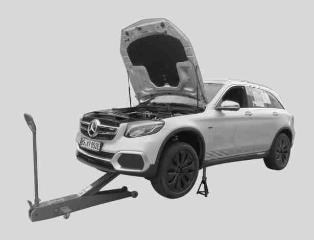
Vehicle in the lifted and secured state |
P06.00-A017-06

P47.60-A020-09
MV | Manual valve |

P47.60-2093-09
1 | Electrical connector | B72/18 | Mean pressure sensor |

2 | Plug |
P06.00-2052-06

4 | Electrical connector |
Y94/7 | Pressure regulating valve 1 |
P06.10-A008-06
Danger | Risk of explosion caused by escaping hydrogen or overheating of the fuel tanks when working on the hydrogen system. Risk of frostbite to body parts caused by escaping gas and by touching component parts carrying gas when emptying fuel tanks. Risk of asphyxiation caused by inhalation of air diluted by hydrogen. Risk of burn injuries by coming into contact with an invisible pale blue hydrogen flame. | ||
Topical note | Information on preventing damage to electronic components due to electrostatic discharge | ||
Topical note | Notes on fuel cell system | ||
Notes on safety-relevant components | |||
Preparatory tasks | |||
1 | Print out the "Manual depressurization event log" form and fill it out during pressure reduction. | ||
| |||
2 | Park vehicle in the open air in the hydrogen discharge area. | ||
3 | Perform quick test for leaks. | ||
If the measured hydrogen concentration is 8000 ppm or there is an audible leak in the fuel cell system, | |||
| |||
Prepare vehicle with major leakage in fuel system for repair | |||
4 | Activate high-voltage disconnect device (S7), as shown in picture sequence (A, B, C), and lock it with a shackle-type lock. | Vehicle is accident-free, but no control unit communication with the fuel tank control unit (N3/19) is possible. | |
For the electrical interruption of the tank components. | |||
Keep the key for the shackle-type lock of the high-voltage disconnect device (S7) in a separate location accessible to authorized personnel only. | |||
5 | Perform a diagnosis-based deactivation of the fuel cell in the powertrain control unit (N127). | Vehicle is accident-free, fault memory can be read out, but there are faulty components in the hydrogen system or a leak that cannot be localized has arisen. | |
| |||
To do this, select the following menu item: | |||
6 | Perform a diagnosis-based deactivation of vehicle standby mode in the powertrain control unit (N127). | Vehicle is accident-free, fault memory can be read out, but there are faulty components in the hydrogen system or a leak that cannot be localized has arisen. | |
| |||
To do this, select the following menu item: | |||
7 | Raise and secure the vehicle at the front with a commercially available vehicle jack or a hydraulic wheel gripper. | Electrical tools are not permitted (explosion protection). | |
8 | In exterior area, remove left center and transmission tunnel underfloor panelings. | ||
Commercially available devices/tools explosion-proof flashlight, comparable with AccuLux flashlight MHL 5 EX of the company Witte + Sutor GmbH. | |||
9 | Seal manual valves (MV) on both fuel tanks. | Commercially available devices/tools explosion-proof flashlight, comparable with AccuLux flashlight MHL 5 EX of the company Witte + Sutor GmbH. | |
The manual valves (MV) can be reached without removing the underfloor paneling. | |||
Torque for sealing of manual valve in valve unit | |||
Manual pressure reduction of the hydrogen high-pressure system to 1 bar | |||
10 | Wear personal protective equipment safety glasses and protective gloves. | Personal protective equipment must always be worn when performing the following operation steps. | |
11 | Cover the high-pressure line beside the medium pressure sensor (B72/18) with a suitable rag. | | |
Commercially available devices/tools explosion-proof flashlight, comparable with AccuLux flashlight MHL 5 EX of the company Witte + Sutor GmbH. | |||
12 | Disconnect electrical connector (1). | Commercially available devices/tools explosion-proof flashlight, comparable with AccuLux flashlight MHL 5 EX of the company Witte + Sutor GmbH. | |
13 | Slowly unscrew the medium pressure sensor (B72/18) two revolutions and wait until pressure reduction has been audibly completed. | ||
Commercially available devices/tools explosion-proof flashlight, comparable with AccuLux flashlight MHL 5 EX of the company Witte + Sutor GmbH. | |||
The medium pressure sensor (B72/18) is subject to approx. 14 bar pressure (hydrogen). | |||
14 | Check the hydrogen tank in the area around the medium pressure sensor (B72/18). | ||
| 000 588 03 21 00 Gas detector | ||
Commercially available devices/tools explosion-proof flashlight, comparable with AccuLux flashlight MHL 5 EX of the company Witte + Sutor GmbH. | |||
specified value under 100 ppm. | |||
15 | Remove the medium pressure sensor (B72/18), check the sealing rings and then re-install them. | ||
Commercially available devices/tools explosion-proof flashlight, comparable with AccuLux flashlight MHL 5 EX of the company Witte + Sutor GmbH. | |||
Ensure scrupulous cleanliness. | |||
If complaints are present, | |||
| |||
replace the sealing ring or medium pressure sensor (B72/18). | |||
Manual pressure reduction of the hydrogen medium-pressure system to 1 bar | |||
16 | Wear personal protective equipment safety glasses and protective gloves. | Personal protective equipment must always be worn when performing the following operation steps. | |
17 | Slowly loosen the stop plug (2) and wait until pressure reduction has been audibly completed. | Commercially available devices/tools explosion-proof flashlight, comparable with AccuLux flashlight MHL 5 EX of the company Witte + Sutor GmbH. | |
Electrical tools are not permitted (explosion protection). | |||
The stop plug (2) is subject to approx. 14 bar pressure (hydrogen). | |||
Ensure cleanliness. No chippings, friction or dirt must enter the fuel cell aggregate. | |||
18 | Check the hydrogen content in the area around the stop plug (2). | ||
| 000 588 03 21 00 Gas detector | ||
Commercially available devices/tools explosion-proof flashlight, comparable with AccuLux flashlight MHL 5 EX of the company Witte + Sutor GmbH. | |||
specified value under 100 ppm. | |||
19 | Unscrew the stop plug (2) completely. | Commercially available devices/tools explosion-proof flashlight, comparable with AccuLux flashlight MHL 5 EX of the company Witte + Sutor GmbH. | |
Store the stop plug (2) in a clean, safe location. | |||
Manual pressure release of fuel cell to below 1 bar | |||
20 | Wear personal protective equipment safety glasses and protective gloves. | Personal protective equipment must always be worn when performing the following operation steps. | |
21 | Disconnect the electrical connector (4) from the pressure regulating valve 1 (Y94/7). | Commercially available devices/tools explosion-proof flashlight, comparable with AccuLux flashlight MHL 5 EX of the company Witte + Sutor GmbH. | |
22 | Connect the power supply unit of the filling device to the pressure regulating valve 1 (Y94/7). | ||
| 000 588 11 82 00 Filling unit | ||
Commercially available devices/tools explosion-proof flashlight, comparable with AccuLux flashlight MHL 5 EX of the company Witte + Sutor GmbH. | |||
23 | Switch on the power supply unit of the filling device and, for 60 s, activate the pressure regulating valve 1 (Y94/7). | ||
| 000 588 11 82 00 Filling unit | ||
Commercially available devices/tools explosion-proof flashlight, comparable with AccuLux flashlight MHL 5 EX of the company Witte + Sutor GmbH. | |||
Switching on the power supply units causes the pressure regulating valve 1 (Y94/7) to open and pressure reduction to start. | |||
When pressure reductions starts, approx. 4 bar pressure (hydrogen) is applied to the pressure regulating valve 1 (Y94/7). | |||
24 | Disconnect the power supply unit of the filling device from the electrical connector (4) on the pressure regulating valve 1 (Y94/7). | ||
| 000 588 11 82 00 Filling unit | ||
Commercially available devices/tools explosion-proof flashlight, comparable with AccuLux flashlight MHL 5 EX of the company Witte + Sutor GmbH. | |||
25 | Connect the electrical connector (4) to the pressure regulating valve 1 (Y94/7). | Commercially available devices/tools explosion-proof flashlight, comparable with AccuLux flashlight MHL 5 EX of the company Witte + Sutor GmbH. | |
26 | Check the hydrogen content in the area around the threaded hole of the stop plug (2). | ||
| 000 588 03 21 00 Gas detector | ||
Commercially available devices/tools explosion-proof flashlight, comparable with AccuLux flashlight MHL 5 EX of the company Witte + Sutor GmbH. | |||
specified value under 100 ppm. | |||
27 | Carefully clean the stop plug (2) and the thread of the pressure regulating valve 1 (94/7). | Commercially available devices/tools explosion-proof flashlight, comparable with AccuLux flashlight MHL 5 EX of the company Witte + Sutor GmbH. | |
Ensure cleanliness. No chippings, friction or dirt must enter the fuel cell aggregate. | |||
Installation: Check O-rings (3) for damage. | |||
If damage is present, | |||
| |||
replace the stop plug (2). | |||
28 | Screw in the stop plug (2). | Commercially available devices/tools explosion-proof flashlight, comparable with AccuLux flashlight MHL 5 EX of the company Witte + Sutor GmbH. | |
Stop plug to pressure regulating valve holder | |||
29 | Inform the market support people in charge immediately as the fuel system will have to be discharged manually. | If one or both fuel tanks have to be removed for the following jobs. | |
Concluding tasks | |||
30 | Park vehicle on the wheels. | ||
31 | Remove U-shackle lock and connect high-voltage disconnect device (S7), as shown in picture sequence (D, E, F). | If the high-voltage disconnect device (S7) has been disconnected, | |
Installation: Check high-voltage disconnect device (S7) for damage. | |||
If damage is present, | |||
| |||
Remove contacts from coupling housing of high-voltage disconnect device (S7) and replace high-voltage disconnect device (S7). | |||
Remove/install contacts from coupling housing of high-voltage disconnect device. | |||
New passenger car wiring harness repair kit | |||
Unlocker with ejector MLK 1.2_plug | |||
Wiring harness repair kit, basic | |||
32 | Localize leakage on fuel cell system. | If damage-causing components or a hydrogen leak is present and cannot be localized. | |
33 | Perform a diagnosis-based activation of vehicle standby mode in the powertrain control unit (N127) and drive the vehicle into the workshop with battery power. | Vehicle is accident-free, fault memory can be read out, but there are faulty components in the hydrogen system. | |
| |||
To do this, select the following menu item: | |||
34 | Slide the vehicle into the workshop. | Vehicle has been in an accident and the airbag or pyrofuses have triggered, or vehicle is accident-free, but no control unit communication with the fuel tank control unit (N3/19) is possible. | |
Use a commercially available hydraulic garage jack to lift and maneuver the vehicle. | |||
35 | Fill out the "Manual depressurization event log, form", sign it and attach it to the vehicle in a clearly visible location. | ||
|


220 589 01 99 25
Unlocker with ejector MLK 1.2_plug
220 589 04 99 00
New passenger car wiring harness repair kit
000 589 13 99 00
Wiring harness repair kit, basic
Henviste dokumenter
- ad0000p200004b
- ah0000p002201rfw Oplysninger om brændselscellesystem
- ah0000z001901a Oplysninger om sikkerhedsrelevante komponenter
- ah5400p000101a Oplysninger med henblik på at undgå skader på elektroniske komponenter på grund af elektrostatisk afladning
- ar0019p012031a
- ar0600p0003rfw
- ar0600p0005rfw
- ar4760p0014rfw Afmontering, montering af tryksensor i trykreguleringsenhed
- ar4760p0018rfw Forberedelse af køretøj til reparation ved høj utæthed i brændstofsystem
- ar6130p1001rfw
- as0000z003001b Fare for eksplosion som følge af udstrømmende brint eller overophedning af brændstoftanke under arbejde på brintanlægget. Fare for forfrysninger på legemsdele som følge af udstrømmende gas og som følge af berøring af gasførende
- of0000p300022rfw Protokol manuel trykreduktion, formular
- ws0600p0028c
- ws4700p0019b