AR01.10-D-2401SD | Remove/install engine with transmission | 23.5.11 |
ENGINES 646.984 /985 /986 /989 /990 in MODEL 906 with TRANSMISSION 711.6
except CODE (ZG1) Engageable all-wheel drive
except CODE (ZG2) Permanent all-wheel drive
except CODE (ZG3) Engageable all-wheel drive with gear reduction
except CODE (ZG4) Permanent all-wheel drive with gear reduction

D01.10-1124-09
1 Cylinder head cover trim panel
2 Coolant hose
3 Pipe clamp
4 Clamp
8 Hydraulic line
9 Refrigerant line (with code (HH9) Regulated air conditioning (Tempmatic))
5 Clamp
6 Fuel hose
7 Fuel hose
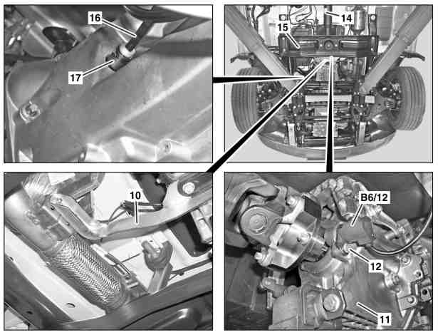
D01.10-1125-06
10 Bracket
11 Transmission
12 Bolt
14 Propeller shaft
15 Rear engine crossmember
16 Hydraulic hose
17 Central clutch release bearing
B6/12 Speed sensor

D01.10-1126-08
18 Bolt
19 Bolt
22 Fan wheel
20 Ground cable
21 Engine
| Remove/install | ||
Danger! | Risk of injury to skin or eyes caused by hydraulic fluid spraying out under high pressure. Risk of poisoning caused by swallowing hydraulic fluid | Depressurize hydraulic system completely before starting any work on system. Wear protective clothing and safety glasses. | |
Danger! | Risk of poisoning caused by swallowing brake fluid. Risk of injury caused by brake fluid coming into contact with skin and eyes. | Only pour brake fluid into suitable and appropriately marked containers. Wear protective clothing and eye protection when handling brake fluid. | |
| Brake fluid notes | ||
1 | Lift/jack up vehicle | ||
2 | Remove engine hood | ||
3 | Remove trim panel for cylinder head cover (1) | ||
4 | Remove front module | ||
5 | Disconnect electrical connector for engine wiring harness at the CDI control unit | ||
6 | Disconnect electrical connectors from the glow output stage. | ||
7 | Disconnect battery lines, loosen battery and push to one side, disconnect the positive line at the terminal and guide down and out of the battery box | ||
8 | Disconnect engine wiring harness | ||
9 | Detach pipe clamp (3) and remove seal cone | Installation: Check seal cone and replace if necessary. | |
| |||
Danger! | Risk of explosion caused by fuel igniting, risk of poisoning caused by inhaling and swallowing fuel and risk of injury to eyes and skin caused by contact with fuel | No fire, sparks, open flames or smoking. Wear protective clothing when handling fuel. | |
10 | Remove hose clamps (4, 5) and pull out fuel hoses (6, 7) | Collect fuel which flows out in a suitable container. | |
11 | Detach coolant hose (2) at coolant pump | ||
12 | Detach refrigerant line (9) at refrigerant compressor | Only on vehicles with code (HH9) Regulated air conditioning (Tempmatic) | |
Seal openings with suitable stop plug. | |||
| |||
13.1 | Remove 2nd refrigerant compressor from carrier and hang up to the side with attached lines | Only for code (H08) Heavy duty air conditioning | |
With code (N63) Engine power take-off wit carrier for additional A/C compressor | |||
13.2 | Remove additional alternator from carrier and lay down to side with connected lines | With code (N62) Engine power take-off wit carrier for additional alternator | |
14 | Disconnect hydraulic line (8) at power steering pump and seal off openings | Remember that hydraulic oil will leak out. | |
| |||
Set of stop plugs | |||
15 | Remove bracket (10) | | |
| |||
16 | Detach shift cables at transmission (11) | ||
Long-life grease | |||
17 | Detach hydraulic hose (16) at central clutch release bearing (17) and seal off openings | Remember that brake fluid will emerge. | |
Set of stop plugs | |||
18 | Remove tamper-proof seal, unscrew bolt (12) and remove speed sensor (B6/12) | Installation: Inspect O-ring, install new ring if necessary. | |
19 | Remove rear engine crossmember (15) | ||
20 | Remove propeller shaft (14) at transmission (11) | Remove the bolts and securely tie up propeller shaft (14) outside the working area. | |
| |||
21 | Remove fan wheel (22) with viscous clutch | | |
Counterholder | |||
22 | Attach engine removal fixture | Mobile workshop crane | |
23 | Unscrew screw/bolt (18) | | |
24 | Unscrew bolt (19) and place ground (20) to one side | | |
25 | Carefully raise engine (21) with transmission (11) and drive out towards the front | Aid of helper required | |
Installation: When replacing engine (21), modify detachable parts. Ensure correct seating of engine mounts (arrows). | |||
26 | Install in the reverse order | ||
27 | Bleed clutch operating system | ||
28 | Check that shift mechanism functions correctly | The transmission (11) must shift smoothly, adjust the shift cables if necessary. See: | |
Adjust transmission shift cables (11) | |||
29 | Attach STAR DIAGNOSIS, read out fault memory, delete if necessary and perform initialization in menu item Control unit adaptation | Only if flywheel or clutch plate has been replaced.. | |
| Connect STAR DIAGNOSIS and read out fault memory | ||
Danger! | Risk of accident caused by vehicle starting off by itself when engine is running. Risk of injury caused by contusions and burns during starting procedure or when working near the engine as it is running | Secure vehicle to prevent it from moving by itself. | |
30 | Conduct engine test run and check engine for leaks |
Exhaust aftertreatment
Number | Designation | Engine | ||
BA14.40-N-1001-02D | Pipe clamp connecting catalytic converter to turbocharger | Nm | 15 | |
BA14.40-N-1006-02D | Nut connecting bracket to catalytic converter | Nm | 23 | |
BA14.40-N-1007-02D | Bolt, bracket to transmission | Nm | 23 | |
Fan, fan clutch
Engine mounts, engine supports
Propeller shaft
Number | Designation | Model | ||||
BA41.10-N-1001-01B | Propeller shaft on transmission | M101 | Stage 1 | Nm | 15 | |
Stage 2 | ° | 90 | ||||
Screw headE14 | Stage 1 | Nm | 15 | |||
Stage 2 | ° | 70 | ||||
M121.5 | Screw headE14 | Stage 1 | Nm | 15 | ||
Stage 2 | ° | 50 | ||||
Screw headE18 | Stage 1 | Nm | 60 | |||
Stage 2 | ° | 60 | ||||
Propeller shaft
Number | Designation | Model | ||||
BA41.10-N-1001-01B | Propeller shaft on transmission | M101 | Stage 1 | Nm | - | |
Stage 2 | ° | - | ||||
Screw headE14 | Stage 1 | Nm | - | |||
Stage 2 | ° | - | ||||
M121.5 | Screw headE14 | Stage 1 | Nm | 15 | ||
Stage 2 | ° | 50 | ||||
Screw headE18 | Stage 1 | Nm | 60 | |||
Stage 2 | ° | 60 | ||||
Power steering pump
Number | Designation | Model | ||
BA46.30-N-1001-01M | High pressure expansion hose to power steering pump | Nm | 38 | |
Air conditioning system
Number | Designation | Model | ||
BA83.30-N-1010-01F | Screw/bolt, refrigerant line to refrigerant compressor | Nm | 22 | |
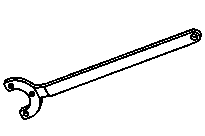

611 589 00 40 00
Counterholder
Set of stop plugs
129 589 00 91 00
Repair materials
Number | Designation | Order number |
BR00.45-Z-1001-06A | Long-life grease | A 000 989 63 51 11 |
Henviste dokumenter
- ad0000d200004sd
- ah4250p000101a Oplysninger om bremsevæske
- ar0060d0100h
- ar0110d240009sd
- ar0120d5015sd
- ar0708d7006sd
- ar1520d4330sd
- ar2210d1170sd
- ar2520d0070sd
- ar2660d662601a Af-, påmontering af gearkabler på gearkasse
- ar2660d6633a Indstilling af gearkabel manuel gearkasse
- ar5410d0005sd Af-, påmontering af batteri
- ar5415d923101se Afbrydelse, tilslutning af motorledningssæt
- ar8830d1064sd
- ar8840d3000sd
- as0000z000501a Fare for ulykke ved automatisk igangsætning når motoren kører. Fare for personskade på grund af knusning og forbrænding, hvis der arbejdes mens motoren startes eller kører
- as0000z001301a Fare for kvæstelser på hud og øjne på grund af sprøjtende hydraulikvæske, som erunder højt tryk. Forgiftningsfare ved indtagelse af hydralikvæske
- as4250z000101a Risiko for forgiftning ved indtagelse af bremsevæske. Risiko for hud- og øjen-skader ved kontakt med bremsevæske
- as4700z000101a Fare for eksplosion ved tænding, fare for forgiftning ved indånding og indtagelse af brændstof samt fare for hud- og øjenskader ved kontakt med brændstof