01-415 Removing and installing cylinder head
Preceding work: Removing air filter (09-400). Draining coolant (20-010). Removing guide rail in cylinder head (05-340). Removing poly V-belt (13-342). | Operation No. of operation texts and operation values or standard texts and flat rates 01-5800 |

P01-0005-57
Fan shroud (1) and fan (75) | remove, install, 25 Nm (steps 1 and 2). |
Cylinder head cover (81) | remove, install (01-406). |
Exhaust pipes (48) | unbolt at exhaust manifold, bolt on (49-100) (step 4). |
Dipstick guide tube (40a) | unbolt, bolt on (step 5). |
Bowden cable (30) | detach, adjust, attach (30-325, step 6). |
Intake manifold strut (160) and return |
unbolt at intake manifold, detach return spring, attach, bolt on (steps 7 and 8). |
Coolant hose (68) supply line for heater | disconnect, connect (step 9). |
Engine wiring harness | disconnect, connect (steps 10 to 14). |
Brake booster vacuum line | disconnect, connect (step 15). |
Fuel cap | open and release pressure in the fuel pipes. |
Fuel pipes | disconnect, connect (step 16). |
Air conditioning pipe group holder | disconnect, connect (step 17). |
Piston of No. 1 cylinder | set to ignition TDC (step 18). |
Alternator | swing out of the road to the outside |
Closing nut (40) | for chain tensioner, remove and install, renew sealing ring (41) (05-310, step 21). |
Camshaft gear (4) | mark relative to timing chain (step 22). |
Pressure oil pump (69) | unscrew, screw on, place to the side with lines connected (step 23). |
Camshaft gear (4) | unscrew, screw on, 80 Nm, check TDC marking (steps 24 and 25). |
Hexagon socket bolts (77) | unscrew, screw on with pin wrench (step 26). |
Cylinder head bolts (75) | unscrew, screw in, check, tighten (steps 27, 31 to 33). |
Cylinder head (51) | take off, fit on, clean mating surfaces, renew cylinder head gasket (74) (steps 28 to 30). The cylinder head gasket (74) is not watertight until the engine has reached normal operating temperature and the gasket has swollen. For this reason, do not pressure-test the cooling system until the engine has reached operating temperature. |
Threaded holes for cylinder head bolts | clean in crankcase. Free of oil and water. |
Engine | warm up to operating temperature. |
Cooling system | check for leaks (20-017). |
Tightening torques in Nm and tightening angle
| |
Cylinder head bolts, engine cold 1st stage 2nd stage tightening angle 3rd stage tightening angle | 55 90° 90° |
Hexagon socket bolts in cylinder head to timing case cover | 25 |
|


Special tools
116 589 03 07 00
001 589 51 21 00
001 589 66 21 00


001 589 72 21 00
617 589 00 10 00

Notes
Take off cylinder head together with camshaft, intake manifold and exhaust manifold once engine has cooled down.
As of 07/1986 an oil nozzle return lock (A) with stop shoulder is installed in the cylinder head.
This oil nozzle must always be installed when performing repairs (18-415).
P01-0191-13
Removal and installation
-------------------------------
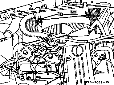
1 Detach fan shroud (1) and place over fan. When installing, ensure proper clearance to fan.
2 Unbolt fan (75) and take out together with fan shroud, bolt on.
3 Remove cylinder head cover together with
spark plug connector and distributor cap
(01-406).
P20-2002-13
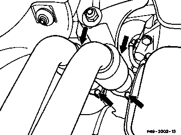
4 Unbolt exhaust pipes at exhaust manifold (49-100).
P49-2002-13
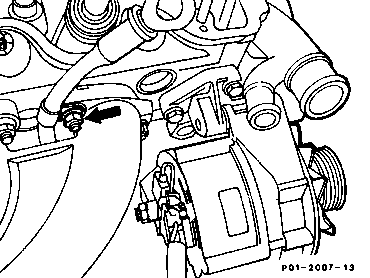
5 Unbolt dipstick guide tube at exhaust manifold (arrow).
P01-2007-13

6 Detach Bowden cable (30) for accelerator control, attach, press plastic guide (arrow) out of its seat in the fulcrum lever (13) to perform this step, and take Bowden cable (30) out of the slot in the fulcrum lever.
Compress plastic clip (28) and push clip together with Bowden cable to the rear through the holder (16).
Adjust Bowden cable (30) (30-325).
P30-2001-13
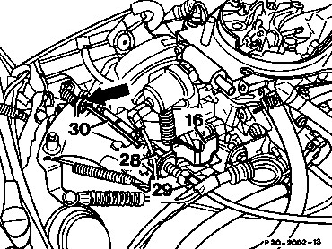
Engines with 2 E-E carburetor
P30-2002-13

7 Unbolt intake manifold strut; to do this on the injection engine, take off 2 hexagon socket bolts (arrows), screw on.
Detach return spring for throttle valve assembly
(below intake manifold), attach.
P01-2024-13

8 If 2 E-E carburetor fitted, unscrew top bolt (161) from strut (160), screw on, 25 Nm.
P01-2023-13

9 Detach coolant hose (68) of supply line for heater, attach.
P20-2004-13

10 Detach connector pickup of control cable (arrow) and 4-pin connector pickup (3) at ignition control unit, plug in.
11 Detach cable from resistance trimming plug (R16) (Model 201 only).
12 Unscrew terminal TD at the diagnostic socket (X11), screw on.
13 Unscrew diagnostic socket (X11), unplug grey cable from the TDC pulse generator at the rear of the diagnostic socket, plug in.
14 Unplug all connectors and vacuum lines at thermo valves and temperature switches, plug in.
P15-2001-13

15 Disconnect vacuum line for brake booster, connect (arrow).
P01-2030-13

16 Dump fuel pressure in the fuel lines by briefly opening fuel filler cap.
Unscrew fuel lines (379, 380), screw on. When detaching the fuel line (380), hold connection to prevent it turning.
P01-2032-13

17 On models with air conditioning: unbolt bracket for AC piping (170) of AC compressor at cylinder head, bolt on.
P01-2031-13

18 Position piston of cylinder 1 to ignition TDC (arrow).
P01-2025-13

19 Slacken bottom bolt (49) for alternator fixture, tighten.
20 Unscrew top bolt (51), swivel alternator out of the way to the outside (arrow).
P15-2038-13

21 Unscrew locking nut (40) of the chain tensioner, screw on. Replace seal (41). Tightening torque 70 Nm (05-310).
P05-2043-13

22 Mark camshaft gear and timing chain relative to each other.
P05-2022-13

23 Unscrew pressure oil pump, place to the side with lines connected, screw on (arrows).
P01-2061-13

24 Unscrew camshaft gear, take off and screw on. Place timing chain in chain box. Tightening torque 80 Nm.
Hold camshaft gear tight with an open-end
wrench (waf 24 mm) for slackening or tightening
the camshaft bolt.
P05-2024-13

25 Check TDC marking on camshaft (arrow).
P05-2008-13

26 Unscrew hexagon socket bolts (arrows) with
the pin wrench 116 589 03 07 00, screw on.
Tightening torque 25 Nm (reference value).
P01-2033-13
27 Unscrew cylinder head bolts in stages in the reverse order of the tightening diagram with the torque wrench insert 617 589 00 10 00 when engine cold.

P01-0094-33
28 Take off cylinder head (51).
29 Clean contact surfaces on cylinder head and crankcase.
30 Replace cylinder head gasket.
The cylinder head gasket (74) is not watertight until the engine has reached operating temperature and the gasket has swollen. For this reason, do not pressure-test cooling system until the engine has reached operating temperature.

31 Check the shaft length of the cylinder head bolts.
If the maximum length (L) of 122 mm is exceeded, the bolts should be replaced by new ones.
32 Clean threaded holes for cylinder head bolts in the crankcase.
Free of oil and water.
33 Oil the thread and head contact surface of the cylinder head bolts and insert.
34 Tighten cylinder head bolts in stages in the order of the tightening diagram, beginning with 1.
1st tightening stage 55 Nm
2nd tightening stage 90° tightening angle
3rd tightening stage 90° tightening angle
Hexagon socket bolts (a), 29 Nm.
P05-0103-13
P01-0094-33
35 Install in the reverse order.
36 Run engine and check for leaks (20-017).