07.1-105 Checking anti-jerk control (ARA) and/or electronic
idle speed control (ELR)
Job no. of Job Texts and Work Units or Standard Texts and Flat Rates 07-2005 and 2006 |

Digital tester (001) and |
connect, disconnect. |
Test with pulse counter | |
Impulse counter (013) to battery (G1) and test coupling (X92) | connect. Note U-Batt LED in display panel must light up; if not: a) check fuse of pulse counter. b) Test contact 1 of test coupling (X92) to batterie positive (approx. 12 V) c) Test contact 4 of test coupling (X92) to battery positive (approx. 12 V) |
Test with hand held tester | |
Hand held tester | connect (see connection diagram of hand held tester). Note Read fault memory, erase; see operating instructions of hand held tester. |
Accelerator control | check for ease of operation. |
Idle speed stop on Bowden cable (230) | check, the spring retainer (226) must touch the compression spring (227) free of tension. |
Overvoltage protection fuse | check. |
Engine | run until coolant temperature 60 - 80 °C. |
Engine | run at idle speed. |
Start button of pulse counter (013) | press for 2 to 4 secondes. |
Display | read and note. |
Start button | press once again; if no new display appears, no further fault in system. |
Test and adjustment data
Engine | Idel speed 1/min Electronic idle speed control (ELR) |
with control | without control | |
601 | 72020 | 66040 |
602 | 68020 | 62040 |
603.912 und 603.9131) | 63020 | 58040 |
603.9132) | 68020 | 62040 |
1) Automatic transmission
2) Manual transmission
Fault memory
Pulse readout | Possible cause |
| No faults stored |
| RPM sensor (L3) |
| ARA actuator (Y22/3), control circuit ARA "short circuit" |
| ARA actuator (Y22/3), control circuit ARA "output stage" interrupt |
| ARA control unit (N 8/2) faulty |
Only short-circuit faults detected on control units with "RO1".
Control units with "RO2" also detect open circuits.
Production breakpoint: Control unit with "RO2" May 1988.
The number of pulses indicates whether and which component is faulty or whether components in the control circuit are faulty.
No system diagnosis is possible on vehicles with Bosch ARA control unit.
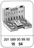
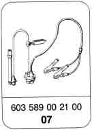

Special tools
Commercially available testers
Designation | e. g. make, order no. |
Multimeter | Sun, DMM-5 |
Digital tester | Bosch, MOT 002.02 |
Additionnal testers
Designation | e. g. make, order no. |
Hand held tester | Mercedes Benz AG 70322 Stuttgart VP/PSD 2 6511 0001 99 |
Multiplexer test cable | Mercedes Benz AG 70322 Stuttgart VP/PSD 2 6511 0040 99 |

Function diagram anti-jerk control/idle speed control
R18/3x | Connector, individual adjustment plug |
W10 | Ground, battery, spring dome |
X92 | Test coupling |
X22 | Electromagnetic actuator ELR (only 603) |
Y22/3 | Electromagnetic actuator ARA |
a | Connector X26 jack 1 terminal 15 |
b | Terminal block (X7) terminal 30 |
B11/1 | Temperature sensor (ELR) |
K1/1 | Overvoltage protection relay |
L3 | Starter ring gear speed sensor |
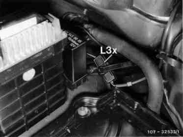
L3x | Connector, starter ring gear speed sensor |
N8/1 | Control unit ARA (ELR) |
R18/3 | Individual adjustment plug (as required) |

P07.10-0224-57
Connection diagram of pulse counter of hand held tester
X92 | Test connector Models 124, 201 |
X11/4 | Data link connector, pulse signal (38-pin) Model 202 |
G1 | Battery |
013 | Pulse counter |
087 | Hand held tester |
075 | Pulse counter adapter |
Pulse counter
Black cable Circuit 31 (gnd) or socket 1
Red cable Circuit 15 (ignition), circuit 30 (battery) or socket 16
Yellow cable Socket 4 (AJC, ESC/AJC control module)
Hand held tester
Black cable Circuit 31 (gnd) or socket 1
White cable Circuit 15 (ignition) or socket 16
Red cable Circuit 30 (battery), X4/10 (terminal block) or socket 3
Yellow cable Socket 4 (AJC, ESC/AJC control module) )
a) Test of engine 601.911/912 up to 01/93
Engine 602, 603
Testing components
-------------------------------
Test overvoltage protection (K1/1)

Check fuse on overvoltage protection. Activation according to electrical wiring diagram.
Switch on ignition, pull off control unit (N8 or N8/1) and measure voltage between the jacks (9 and 11).
Display: approx. 12 V DC
End of test
Yes
No
Impulse display "2"
Yes
No
Checking speed sensor
Engine switched off. Pull off double coupling (L3x). Connect multimeter to pins of double coupling and press key "W". Measure resistance.
Display: AB Elektronik 1000 10W
Beru 530 10W
VDO 1900 10W
Renew starter ring gear speed sensor (L3).
End of test
Multimeter connection as above, press key "V". Run engine at idle speed.
Display: > 4 V AC
Voltage rises with increasing speed.
Inspect starter ring gear speed sensor for accumulation of dirt or metal chips, clean if required.
Yes
No
Impulse display "3"


End of test
Check voltage on 1-pole coupling "Ignition" On.
Display: approx. 5 V
Renew coolant temperature sensor.
Yes
No
Checking coolant temperature sensor (B11/1)
Engine switched off. Pull plug off temperature sensor and check resistance against ground. Set values see diagram. Measure resistance at two temperature measuring points.
Example:
+20 °C=2,2-2,8 kW
+80 °C=290-370 W
Eliminate line interruption. Renew control unit (N8 or N8/1).
End of test
Yes
No
Impulse display "5" (function check)


End of test
Until 08/89
Increase engine speed to 900/min.
Briefly actuate control lever several times, short misfiring is noticeable.
"ARA operational".
Check lines according to wiring diagram. Check fuse of overvoltage protection K1/1.
If lines are OK, renew control unit ELR (N8/1 or N8/2).
Pull double coupling off ARA electromagnetic actuator (Y22/3).
Briefly connect battery voltage to ARA electromagnetic actuator (Y22/3) (max. 3 s).
Idle speed drops.
Renew electrom. actuator.
End of test
Yes
No
Yes
No
As of 09/89
Check voltage on double coupling of ARA electromagnetic actuator:
Press multimeter key "V=".
Engine idling - briefly accelerate full throttle.
Voltage rises.
Yes
No
Impulse display "6"
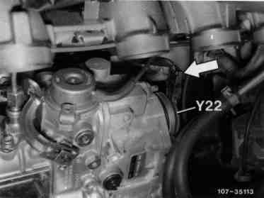

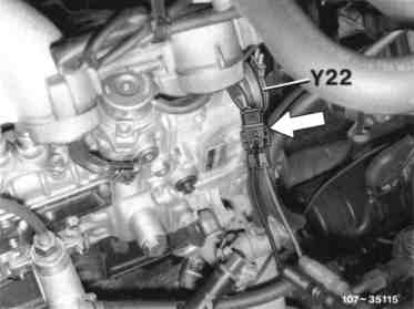
Engine idling. Pull double coupling (arrow) off ELR electromagnetic actuator (Y22) for at least 3 s and reconnect.
Upon reconnecting, the idle speed briefly exceeds the governed idle speed.
Apply battery voltage to ELR electromagnetic actuator (Y22) for a maximum of 3 s.
Caution! If the voltage is applied for longer than 3 s, the ELR electromagnetic actuator will be damaged.
Idle speed rises.
Renew electrom. actuator.
End of test
End of test
Yes
No
Yes
No
Engine idling. Remove double coupling (arrow) from electromagnetic actuator (Y22).
Connect multimeter and set to "V=".
Display: approx. 12 V
Yes
No
Check lines according to wiring diagram. Check fuse of overvoltage protection relay K1/1.
If lines are OK, renew control unit (N8/1).

Loosen lock nut and adjust idle speed (arrow).
left = higher
right = lower
End of test
Engine idling. Pull double coupling (arrow) off ELR electromagnetic actuator (Y22).
Check idle speed.
Set values:
Engine Idle speed/min
601 66040
602 62040
603.912+603.913
with automatic transmission 58040
603.913
with manual transmission 62040
Yes
No
Pulse display "7" and "9" see section "b" test of engine 601.912 as of 02/93, 601.913.
Checking individual adjustment plug (R18/3)
(if available)


End of test
Display: approx. 5 V
Individual adjustment plug (R18/3)
Engine switched off. Pull individual adjustment plug off double coupling.
Glow starter switch in position "2". Set multimeter to "V=" and measure voltage.
Eliminate line interruption.
Renew individual adjustment plug (see table).
Yes
No
Table individual adjustment plug
Part no. | Resistance in | No. | Complaint |
000 540 29 81 000 540 22 81 000 540 23 81 | 100 W 220 W 470 W | I II III | 3 different resistors can be optionally installed to combat "part-load jerking". Start with no. I in ascending order. After change, test-drive vehicle. |
000 540 25 81 000 540 26 81 000 540 27 81 | 1300 W 2400 W 4700 W | I II III | 3 different resistors can be optionally installed to combat "poor acceleration". If too high a resistor is selected, the jerking gets worse. After the change, test-drive vehicle. |
Note
In order to change the individual adjustment plug it is necessary to switch off the "ignition" as the new adjustment will otherwise not be identified by the control unit.
In order to establish the amount of the resistance it is possible to simulate the adjustment plugs in the above table with the ohm decade.
b) Testing engine 601.912 as of 11/92,
Engine 601.913
Pulse display | Test step/ | Tester/test connection | Operation/ | Specifi- | Possible cause/remedy |
| 1.0 | - | - | - | no fault stored |
| 2.0 Starter ring gear sensor (L3) Voltage | N8/2 10 12 | Control unit (N8/2) removed Engine: start | >10 V 1) | L3, clearance, dirt |
2.1 Resistance | N8/2 10 12 | Control unit (N8/2) removed | Beru 10 % VDO 1900 W 2) | L3 L3x1
| |
or3) | 3.0 ARA actuator (Y22/3) Voltage supply | Y22/3 1 2 | Engine: start Idling speed Connector at servomagnet Y22/3 disconnected Briefly depress to full throttle | Voltage rises | ARA control unit (N8/2) Wiring |
3.1 Resistance | N8/2 5 9 | Control unit (N8/2) removed | 2,50,25 W 2) | Y22/3 x26/2 Wiring | |
3.2 | Y22/3 N8/2
2 5 | Control unit (N8/2) and coupling (Y22/3) unplugged | <1 W | Wiring x26/2 | |
3.3 | Y22/3 N8/2 1 9 | Control unit (N8/2) and coupling (Y22/3) unplugged | <1 W | Wiring x26/2 | |
| ARA control unit (N8/2) | ARA control unit (N8/2) | |||
1) Voltage rises as engine speed rises
2) Measured at 20 °C ambient temperature (each 10 °C change in ambient temperature alters resistance by 4 %)
3) Air guide housing removed
เอกสารที่อ้างถึง
- ra07016010001x
- ra07016010002x
- ra07016010003x
- ra0701601a010x
- ra0701601a015x
- ra0701601b010x
- ra0701601b015x
- ra0701601c010x
- ra0701601c015x
- ra0701601d010x
- ra0701601e010x
- ra0701601f010x
- ra0701601g010x
- ra0701601h010x
- ra0701601i010x
- ra0701601j010x
- ra0701601k010x
- ra0701601l010x
- ra0701601m010x
- ra0701601n010x
- ra0701601o010x
- ra0701601p010x
- ra0701601pr02x
- ra0701601q010x
- ra0701601r010x
- ra0701601ta00x