
Shown on engine 654 without code M014 (Engine uprated) |
1 | Diesel particulate filter |
2 | Clip |
3 | Union nut |
4 | Charge air pipe |
9 | Turbocharger |
10 | Electrical wiring harness |
11 | Bracket |
12 | Bolts |
P49.10-3230-06

Shown on engine 654 without code M014 (Engine uprated) |
1 | Diesel particulate filter |
13 | Differential pressure sensor |
14 | Exhaust gas recirculation line |
15 | Bolts |
17 | Screw |
P49.10-3138-06
Warning | Risk of burn injuries, suffocation and poisoning when working on the exhaust system and the components connected to it. Risk of suffocation and risk of poisoning caused by inhalation of gaseous and solid components of the exhaust. Risk of poisoning caused by skin contact with solid components of the exhaust. | Wear protective clothing and safety glasses. Use the extraction system. Move people out of the hazard area. | |
Warning | Risk of injury to skin and eyes suffering scalding from contact with hot coolantspray. Risk of poisoning from swallowing coolant. | Do not open cooling system unless coolant temperature is below 90 °C. Open cap slowly and release the pressure. Do not pour coolant into beverage containers. | |
Caution | Risk of injury caused by scraping or cutting body parts on sharp vehicle parts | Always wear protective gloves when working on or near sharp and non-deburred vehicle parts. | |
Topical note | Notes on avoiding damage through contamination and foreign objects | ||
Topical note | Notes on coolant | ||
Topical note | Notes on self-locking nuts and bolts | ||
Notes on coolant level | |||
Note on calculation of tightening torque when using insertion or socket tools with various effective lengths | |||
| Remove/install | ||
1 | Remove the catalytic converter. | ||
2 | Remove DPF differential pressure sensor (B28/8) with bracket; release and disconnect electrical connector. | ||
3 | Remove air intake line upstream of exhaust gas turbocharger (9). | ||
4 | Remove union nut (3), remove pressure line, and seal openings with suitable stop plugs. | Union nut, pressure line to diesel particulate filter | |
Record plug | |||
Box wrench bit | |||
5.1 | Remove charge air pipe (4). | Engine 654 in model 205.### 1# , 253.### 1# | |
Bolt, bracket for charge air pipe to charge air pipe/exhaust gas turbocharger | |||
Screw/bolt to connection for charge air line to charge air line | |||
Screw/bolt, charge air line to support | |||
Set of protective covers | |||
5.2 | Remove the air duct housing. | Engine 654 in model 205.### 1# , 253.### 1# | |
6 | Remove right heat shield under diesel particulate filter (1). | ||
Bolt, heat shield for diesel particulate filter to timing case/crankcase/bracket for exhaust gas turbocharger/engine support/bracket | |||
7 | Remove exhaust system from diesel particulate filter (1). | ||
8 | Unclip electrical wiring harness (10) from the bracket (11). | ||
9 | Remove screws (12). | Bolt, bracket to diesel particulate filter | |
10 | Remove screw (17). | Bolt, bracket to diesel particulate filter | |
11 | Remove screws (15) and remove exhaust gas recirculation line (14). | Installation: Replace screw/bolts (15). | |
Bolt, connecting point for high pressure EGR line | |||
Bolt, high pressure EGR line to high pressure exhaust gas recirculation valve | |||
12 | Seal openings using suitable protective covers. | Set of protective covers | |
Set of protective caps | |||
13 | Suction off coolant from coolant expansion reservoir. | If necessary. | |
Hand pump | |||
14 | Remove bleed line at the coolant expansion reservoir, place it to one side, and seal openings using suitable stop plugs. | ||
Record plug | |||
15 | Open clamp(2). | Installation: Replace seal. | |
Bolt, clamp for low pressure EGR line to diesel particulate filter | |||
16 | Remove diesel particulate filter (1). | Aid of helper required. | |
17 | Modify pressure lines with DPF differential pressure sensor (B28/8). | When replacing the diesel particulate filter (1). | |
Union nut, pressure line to diesel particulate filter | |||
Box wrench bit | |||
18 | Remove combustion and corrosion residue at connecting points. | ||
19 | Install in the reverse order. | ||
| Check | ||
20 | Check engine cooling system for leak tightness. |
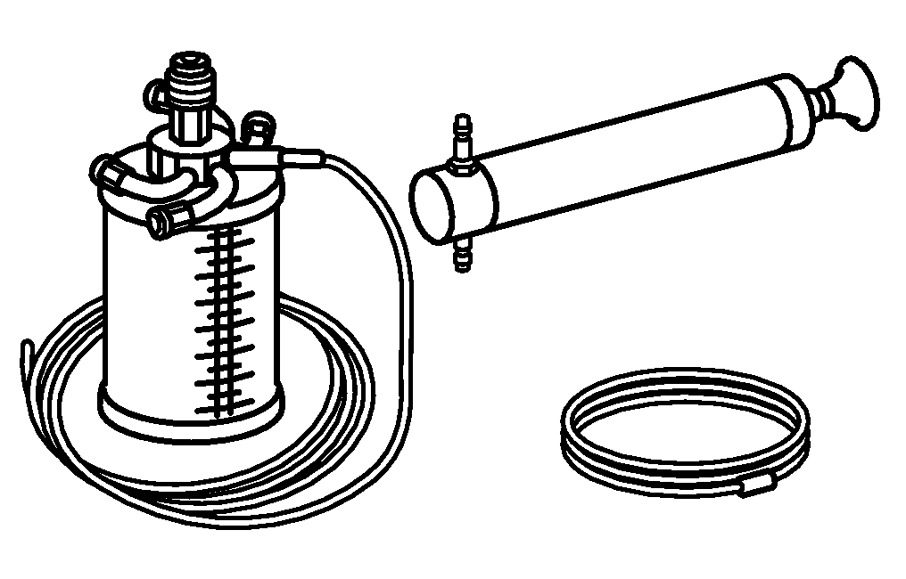


210 589 00 71 00
Hand pump
001 589 00 91 00
Set of protective caps
129 589 00 91 00
Record plug
000 589 70 03 00
Box wrench bit

001 589 01 91 00
Set of protective covers