
Shown on engine 654 without code M014 (Engine uprated) |
1 | Catalytic converter |
2 | Heat shield |
3 | Electrical connector |
4 | Electrical connector |
5 | Electrical line |
6 | Impact plate |
P14.40-2589-06
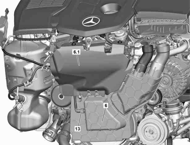
Shown on engine 654 with code M014 (Uprated engine) |
6 | Impact plate |
6.1 | Noise insulation |
13 | Plug-in connector |
P14.40-2652-06
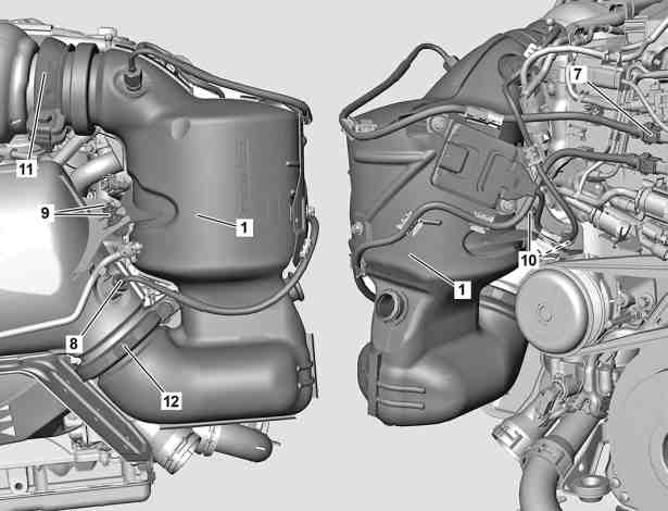
Shown on engine 654 without code M014 (Engine uprated) |
1 | Catalytic converter |
7 | Electrical connector |
8 | Temperature sensor for diesel particulate filter |
9 | Bolts |
10 | Bolts |
11 | Pipe clamp |
12 | Pipe clamp |
P14.40-2590-06
Warning | Risk of injury. Skin or eye injuries may result when handling hot or glowing objects. | Wear protective gloves, protective clothing and safety glasses, if necessary. | |
Warning | Risk of burn injuries, suffocation and poisoning when working on the exhaust system and the components connected to it. Risk of suffocation and risk of poisoning caused by inhalation of gaseous and solid components of the exhaust. Risk of poisoning caused by skin contact with solid components of the exhaust. | Wear protective clothing and safety glasses. Use the extraction system. Move people out of the hazard area. | |
Caution | Risk of injury caused by scraping or cutting body parts on sharp vehicle parts | Always wear protective gloves when working on or near sharp and non-deburred vehicle parts. | |
Topical note | Notes on self-locking nuts and bolts | ||
Topical note | Notes on avoiding damage through contamination and foreign objects | ||
| Remove/install | ||
1 | Remove fan unit. |
| |
Engine 654 in model 253.### 1# | |||
Installation: Only install upper engine cover after the leak test. | |||
2 | Attach protective plate for cooler. | ||
| |||
3 | Remove noise insulation (6.1). | Engine 654 in model 205, 253 | |
4 | Release and disconnect connector coupling (13) of vacuum line. | Engine 654 in model 205, 253 | |
5 | Remove impact plate (6). | ||
6 | Release and disconnect electrical connector (7). | ||
7 | Release and disconnect electrical connectors (3, 4) and unclip electric lines (5) on catalytic converter (1). | ||
8 | Remove differential pressure sensor from heat shield (2) and place to one side with lines connected. | ||
9 | Remove heat shield (2). | ||
10 | Remove exhaust aftertreatment system injection nozzle from catalytic converter (1) and place to one side with lines connected. | ||
11 | Release and disconnect electrical connector of diesel particulate filter temperature sensor (8) and unclip electric line on catalytic converter (1). | ||
12 | Open pipe clamp (11). | Installation: Replace seal. | |
Clamp/flange connection catalytic converter to exhaust gas turbocharger | |||
13 | Open pipe clamp (12). | Installation: Replace seal. | |
Clamp to catalytic converter and diesel particulate filter | |||
14 | Remove screws (10). | Bolt, catalytic converter to bracket | |
15 | Remove screws (9). | Bolt connecting diesel particulate filter to catalytic converter | |
16 | Remove catalytic converter (1) upwards. | ||
17 | Remove temperature sensor from catalytic converter (1). | When replacing catalytic converter (1). | |
18 | Remove NOx sensor with controller unit. | When replacing catalytic converter (1). | |
19 | Install in the reverse order. | ||
20 | Read out and delete fault memory. | ||
| |||
Warning | Risk of accident from vehicle starting off by itself when engine running. Risk of injury (bruises and burns) resulting from working on the engine while it is being started or when it is running. | Secure vehicle to prevent it from starting off by itself. Wear closed and snug-fitting work clothes. Do not touch hot or rotating parts. | |
21 | Carry out engine test run and check engine for proper leaktightness and leaktightness. | ||
22 | Install upper engine cover. |