
P33.10-2285-06
1 Cold air intake bridge
2 Cable tie
3 Radiator crossmember
4 Diagonal struts
10 Front axle carrier
15 Screw
18 Bolts
19 Vehicle jack support point

P33.10-2284-09
5 Tie rod
6 Steering knuckle
7 Steering coupling
7a Electrical connector
7b Screw
8 Link rod
16 Rack-and-pinion steering
17 Bolts
18 Bolts
Y10 Speed-sensitive power steering solenoid valve
9 Stabilizer bar
10 Front axle carrier
11 Cross strut
12 Torque strut
13 Linkage rod
14 Bracket

P33.10-2312-08
4 Diagonal strut
10 Front axle carrier
11 Cross strut
23 Radiator seat
24 Rubber mounts
20 Bracket
21 Lower oil line
22 Support strut
Modification notes
23.11.10 | Value changed: Bolt, clamp plate, high-pressure line / return line to rack-and-pinion steering control head | Model 204 without 4-MATIC Model 204 with 4-MATIC | |
25.11.10 | Value changed: Bolt, clamp plate, high-pressure line / return line to rack-and-pinion steering control head | Model 207 |
| Remove/install | ||
Danger! | Risk of injury to skin or eyes caused by hydraulic fluid spraying out under high pressure. Risk of poisoning caused by swallowing hydraulic fluid | Depressurize hydraulic system completely before starting any work on system. Wear protective clothing and safety glasses. | |
| Notes on self-locking nuts and bolts | ||
While working on the front axle care must be taken to ensure that the surfaces of aluminum components do not get any scratches, cracks and notches. Otherwise the service life of the of the parts will be reduced. | |||
Installation: Tighten nuts and bolts of chassis components only when vehicle is in the ready-to-drive condition. | |||
1 | Secure vehicle on vehicle lift | ||
2 | Deactivate easy entry/exit function | Vehicles with memory package (driver seat, steering column, mirrors) code 275 | |
3 | Move front wheels to straight-ahead position and secure steering wheel. | The steering wheel must not be turned when the steering coupling is detached, otherwise the clock spring contact will be destroyed. | |
| |||
4 | Remove cold air intake crossmember (1) | ||
5 | Fasten radiator on the left and right to radiator crossmember (3) with cable ties (2) | ||
6 | Extract oil from power steering expansion reservoir | | |
7 | Remove the front wheels | ||
| Remove/install wheels | ||
8.1 | Remove both lower engine compartment paneling | Model 204.9 | |
Installation: Only install engine compartment paneling after leak check on the rack-and-pinion steering (16). | |||
8.2 | Remove engine compartment paneling | Model 204 except model 204.9, 207 with gasoline engine | |
Installation: Only install engine compartment paneling after leak check on the rack-and-pinion steering (16). | |||
8.3 | Remove lower bottom sections of soundproofing | Model 204 except model 204.9, 207 with diesel engine | |
Installation: Install bottom sections of soundproofing only after leak check on rack-and-pinion steering (16). | |||
| Carry out steps 9 to 13 only on vehicles without 4MATIC | ||
9 | Detach tie rods (5) from steering knuckles (6) | ||
| |||
| |||
Tie rod ball joint without stainless steel ring | |||
Tie rod ball joint with stainless steel ring | |||
| |||
10 | Detach bracket (14) of linkage (13) from torsion bar (9) | Vehicles with bi-xenon headlamps | |
11 | Remove link rods (8) on stabilizer bar (9) | If necessary, counterhold ball head bolt with internal torx. | |
| |||
12 | Remove cross struts (11) from front axle carrier (10) | ||
13 | Detach torque struts (12) from front axle carrier (10) | ||
14 | Remove front axle shafts | Vehicles with 4MATIC | |
15 | Separate steering coupling (7) | ||
16 | Separate electrical connector (7a) on speed-sensitive power steering solenoid valve (Y10) and unclip retaining clip from front axle carrier (10) | Vehicles with code (213) Speed-sensitive power steering | |
17 | Remove bolt (15) from bracket of hydraulic line on front axle carrier (10) | ||
18 | Remove screw from hydraulic line to rack-and-pinion steering (16) | Vehicles with 4MATIC | |
19 | Remove bolt (7b) and pull out hydraulic lines on rack-and-pinion steering (16) | Seal line connections. | |
Installation: Replace sealing rings. | |||
| |||
| |||
20 | Unscrew nut of bracket (20) from wheelhouse oil cooler on front axle carrier (10) | Model 204 with engine 156 | |
21 | Detach lower oil line (21) on wheelhouse oil cooler | Model 204 with engine 156 | |
22.1 | Remove bolts (17) from below from the engine mounts | Vehicles without 4MATIC | |
| |||
22.2 | Remove bolts from above from the engine mounts | Vehicles with 4MATIC | |
| |||
23 | Mount engine hoist | ||
24 | Lift engine a little | ||
25.1 | Remove rear section of front wheel well panel | Model 204.9 | |
25.2 | Loosen wheel house lining in area of diagonal struts (4) | Model 204 except 204.9, 207 | |
26 | Detach front door sill panels | ||
27 | Remove diagonal struts (4) | Installation: The bolts of the diagonal struts (4) may only be securely tightened when the vehicle is standing with its wheels on the ground. | |
| |||
| |||
28 | Support front axle with transmission jack and lash down securely | ||
29 | Detach support strut (22) on vehicle underbody and detach front axle carrier (10) | Model 204 with engine 156, 204.9, 207 | |
| |||
30 | Remove bolts (18) from longitudinal members | Installation: Replace bolts (18). | |
| |||
31 | Lower front axle carrier (10) | Installation: Pay attention to correct seat of the rubber supports (24) for the radiator support (23). | |
| Checking | ||
32 | Check front axle carrier (10) for damage | Replace if necessary. | |
33 | Check radiator supports (23) and rubber supports (24) for damage and replace if necessary | Replace if necessary. | |
| Perform operation steps 34 to 37 only when replacing front axle carrier (10) | ||
34 | Remove clamps for engine compartment paneling or bottom sections of soundproofing | ||
35 | Remove vehicle jack support point (19) | ||
36 | Remove stabilizer bar (9) | ||
37 | Remove rack-and-pinion steering (16) | ||
38 | Install in the reverse order | ||
39 | Fill power steering pump and bleed | ||
40 | Perform wheel alignment check | Model 204 | |
Model 207 |
Tie rod
Number | Designation | Model | Model | ||
BA46.40-P-1001-01N | Self-locking nut, tie rod to steering knuckle | Stage 1 | Nm | 50 | 50 |
Stage 2 | ° | 60 | 60 | ||
Front axle stabilizer bar
Steering gear
Number | Designation | Model | Model | |||
BA46.20-P-1003-01N | Bolt, clamp plate, high-pressure line / return line to rack-and-pinion steering control head | Nm | 21 | 21 | ||
Steering gear
Number | Designation | Model | Model | |||
BA46.20-P-1003-01N | Bolt, clamp plate, high-pressure line / return line to rack-and-pinion steering control head | Nm | 21 | 21 | ||
Engine mount, engine support (engine side)
Number | Designation | Model | Model | Model | Model | ||
BA22.10-P-1002-03E | Bolt, front engine mount to front axle carrier | Nm | 28 | 28 | 28 | 28 | |
Engine mount, engine support (engine side)
Number | Designation | Model | Model | ||
BA22.10-P-1002-03E | Bolt, front engine mount to front axle carrier | Nm | 28 | 28 | |
Front axle carrier
Number | Designation | Model | Model | ||
BA33.10-P-1001-01M | Bolt, front axle carrier to longitudinal member | Nm | 180 | 180 | |
BA33.10-P-1002-01M | Fixing of support (strut) | Nm | 110 | 110 | |
Frame floor assembly
Number | Designation | Model | Model 207.3 | Model 207.4 | ||
BA61.10-P-1004-01H | Bolt, diagonal strut mount on front axle carrier/longitudinal member | Nm | 50 | 50 | 80 | |
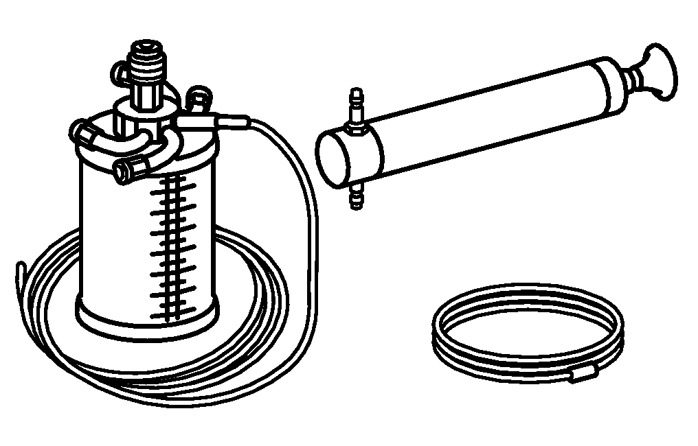


210 589 00 71 00
Set of stop plugs
Hand pump
Holding device
Thrust piece
129 589 01 21 00
129 589 00 91 00
171 589 00 34 00


163 589 03 43 00
Set of engine bearing wrenches
Press
Puller
Puller
221 589 00 33 00
001 589 01 16 00
221 589 05 33 00