
1 | Camshaft positioner |
2 | Control valves |
3 | Timing chain |
4 | Camshafts |
5 | Hold-down tool |
6 | Bracket |
P05.20-2512-06
Caution | Risk of injury caused by scraping or cutting body parts on sharp vehicle parts | Always wear protective gloves when working on or near sharp and non-deburred vehicle parts. | |
Caution | Risk of injury to skin and eyes due to handling of engine oil. Risk of poisoning caused by swallowing engine oil | Wear protective gloves, protective clothing and safety glasses. | |
Warning | Risk of injury. Moving parts can pinch, crush or, in extreme cases even sever extremities. | No parts of the body or limbs should be within the operating area of mechanical components when moving components. | |
Topical note | Notes on avoiding damage through contamination and foreign objects | ||
| Remove/install | ||
1.1 | Remove engine air intake duct upstream of air filter. | Engine 274.9 in model 167 | |
Installation: Only install upper engine cover after the leak test. | |||
1.2 | Remove right charge air line and place charge air cooler towards front with connected lines. | Engine 264 in model 167 | |
Installation: Only install right charge air line and charge air cooler after checking basic position of camshafts (4). | |||
2 | Turn engine at center bolt of crankshaft in direction of engine rotation to top dead center (ignition TDC) of cylinder 1. | The TDC marking on belt pulley/ vibration damper must be aligned with positioning edge on timing case cover. | |
Socket wrench bit | |||
3 | Remove cylinder head cover. |
| |
Engine 264 in model 167 | |||
4 | Install hold-down tool (5) with brackets (6). | | |
| |||
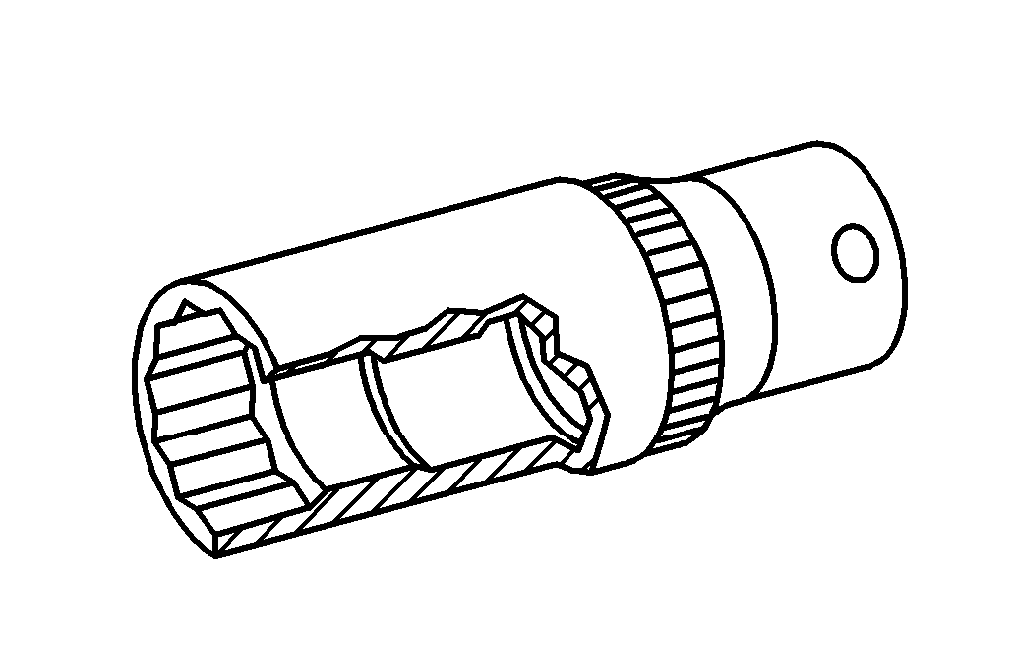
Socket | |||
Holding device | |||
5 | Mark position of timing chain (3) relative to corresponding camshaft positioner (1). | ||
6 | Remove the chain tensioner. | ||
7 | Unscrew control valve (2) of corresponding camshaft positioner (1). | ||
Topical note | Notes on threaded connections fastened using a tightening angle-based tightening process | ||
| Specified engine oils for Cars, Vans (service) - Overview | ||
Installation: Wet thread and bolt head contact surface of control valve (2) with engine oil. | |||
Engine 274.9 in model 167Center valve, pulse wheel/camshaft adjuster to camshaft | |||
Engine 264 in model 167Control valve of pulse wheel/camshaft positioner to camshaft | |||
Socket wrench bit | |||
8 | Lift off timing chain (3) from the corresponding camshaft positioner (1) and remove corresponding camshaft positioner (1). | Installation: Observe marking. | |
| Check | ||
9 | Check toothing of camshaft positioner (1) for damage and wear. | If there is a problem, | |
| |||
Replace camshaft positioner (1). | |||
10 | Install in the reverse order. | ||
| Check | ||
11 | Check basic position of camshafts (4). | ||
Warning | Risk of accident from vehicle starting off by itself when engine running. Risk of injury (bruises and burns) resulting from working on the engine while it is being started or when it is running. | Secure vehicle to prevent it from starting off by itself. Wear closed and snug-fitting work clothes. Do not touch hot or rotating parts. | |
12 | Perform engine test run. While doing so, check engine for proper operation and leak tightness. |



270 589 01 61 00
Holding device
001 589 65 09 00
Socket wrench bit
270 589 01 07 00
Socket
177 589 00 09 00
Socket wrench bit
Documente menționate
- ah0000p002001a Indicaţii referitoare la îmbinările filetate, care au fost realizate conform procedeului de strângere în funcţie de unghiul de rotire
- ah0000p500001a Indicaţii pentru evitarea defecţiunilor din cauza impurităţilor şi corpurilor străine
- ar0120p5014mrk
- ar0120p5014mrm
- ar0510p7800mrk
- ar0520p6010mrk
- ar0941p6817mrk
- as0000z000501a Pericol de accident prin pornirea de pe loc cu motorul aflat în funcţionare. Pericol de rănire prin striviri şi arsuri la manipularea în timpul pornirii motorului sau cu motorul aflat în funcţionare
- as0000z000901a Pericol de rănire prin prinderea sau strivirea, în caz extrem prin tăierea membrelor în timpul manipulării sistemului mecanic
- as0000z001701a Pericol de rănire prin tăieturi respectiv zgârieturi provocate de componentele cu muchii ascuţite ale autovehiculului
- as1800z000101a Pericol de rănire a pielii şi ochilor la manipularea uleiului de motor. Pericol de intoxicare prin înghiţire de ulei de motor
- bb0040p022302a Uleiuri de motor prescris pentru autoturisme, transportoare (service) - Listă