AR35.31-P-0550-13B | Calculating shim and installing in rear axle housing | Use data sheet: | |
Data sheet, rear axle ring and gear pinion setting: Order No. 6516 7422 00 D |
German passenger car data sheets |
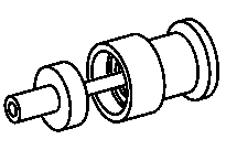


201 589 05 21 00
201 589 04 21 00
363 589 02 21 00
601 589 00 23 00
Measuring device
Measuring plate
Dial gage holder
Measuring device

000 589 38 19 00
Dial gage

P35.31-0262-01
1 Clamp commercially available dial gage into dial gage holder 363 589 02 21 00 and position on measuring plate 601 589 00 23 00.
2 On gauging member (051b) 201 589 05 21 00 Part 01 set dial gage to "0" with approx. 3 mm pre-tension; the height of the gauging member "B1" is therefore regulated.

P35.31-0263-01
3 Place tapered roller bearing outer race (46b) onto the tapered roller bearing inner race of the drive pinion (47), and position magnetic disk (052c) 201 589 04 21 00 Part 16.
4 Insert drive pinion into the measuring plate and measure the height of the drive pinion with tapered roller bearing and magnetic disk.
5 Enter digit 1 in the data sheet.
Read off the difference between the height of the gauging member "B1" and the height of the drive pinion with magnetic disk "B", and enter in the data sheet under digit 1 (e. g. 0.88 mm).

P35.31-0364-01
6 Enter digit 2 in the data sheet.
Read off the basic deviation "a" of the drive pinion (+ or -) and enter under digit 2
(e. g. +0.27) in the data sheet.
7 Calculate the intermediate total in the data sheet.
Depending on the prefix (+ or -) of the value at the drive pinion, add (+) or subtract (-) the values of digit 1 and 2.

P35.31-0365-01
8 Insert gauging member (051b) 201 589 05 21 00 Part 01 of the measuring device into the rear axle housing. Screw gauging member with fastening piece 201 589 05 21 00
Part 02 and hex screw.

P35.31-0267-01
9 Insert dial gage (052a) 000 589 38 19 00 with measuring pin into the measuring device (052)
201 589 04 21 00.
Measuring pin for the dial gage is screwed in at the adjustment piece (052b).
10 Press adjustment piece (052b) 201 589 04 21 00 Part 10 against the measuring device and set dial gage to "0" with 2 mm pre-tension. Tighten clamp screw, whilst doing so check the "0" position of the dial gage, readjust if necessary.

P35.31-0366-01
11 Insert the measuring device (052) from the left drill hole into the rear axle housing.
When inserting the measuring device (052) into the rear axle housing, ensure that the measuring pin of the dial gage is not damaged on the drill hole.

P35.31-0270-02
12 Enter digit 3 in the data sheet.
Measure the difference "A1" between the set gage dimension and the gauging member face, and under digit 3 in the data sheet in a positive (+) or negative direction (-)
(e. g. -0.28 mm measured and therefore negative direction).
Specification of the positive (+) or negative (-) direction refers to the direction in which the dial gage indicator rotates.
The direction of rotation, from the neutral position, in a counter-clockwise direction therefore indicates the negative direction, and clockwise indicates the positive direction.
13 Calculate the thickness of the shim "S" in the data sheet.
Add (+) or subtract (-) the intermediate total of the values from digit 1 and digit 2, and the value from digit 3. The calculated value reveals the thickness of the shim.
051b Gauging member
A1 Difference between gage dimension and gauging member face
B1 Height of the gauging member
M Center of ring gear
Example:
1. | Measure the difference between the height of the gauging member "B1" and the height of the drive pinion with magnetic disk "B" |
= |
0.88 | ||
2. | Read off the basic deviation "a" at the drive pinion | = | + | 0.27 | |
= | - | ||||
Intermediate total | = | 1.15 | |||
3. | Measure the difference "A1" between the set gage dimension and the gauging member face |
Negative direction |
= |
+ |
0.28 |
Positive direction | = | - | |||
Thickness of the shim "S" | = | 1.43 |

P35.31-0367-01
14 Remove the measuring device (052) from the rear axle housing. Remove the gauging member (051b).
15 Insert the shim with the calculated shim thickness "S" into the rear axle housing.
Only hardened shims may be used. These are available in various thicknesses (see parts microfiche). If necessary, grind the shim off accordingly.